Carlson Tip of the Day… Virtually “printing” to PDF, DWF, JPG and PNG files

Penwill CartoonsIf you’ve recently switched from an AutoCAD-based program to Carlson with IntelliCAD, one thing you may miss is having the ability to virtually “plot” your drawings to PDF, DWF, JPG and PNG files instead of to paper. This functionality is not included in IntelliCAD and, from what I understand, including it would have significantly increased the price of each license so the developers decided to leave it out and allow users to purchase add-on programs if needed the functionality.

So, if you need to print to one of these formats, how can you do it?

If you primarily need to create PDF files and don’t mind spending some kinda-big bucks, you can purchase a program such as Adobe AcrobatAcrobat is a standalone program but it also installs as a virtual printer into Windows-based programs like Carlson, AutoCAD and even Microsoft Windows and Outlook.

If you need to print to PDF, you could save some money and consider other after-market programs such as CutePDF or PDF995 (or many others) that essentially serve the same purpose – installing as a PDF printer into Windows-based programs. Most of these programs have a free version but there’s usually a catch such as a watermark on each PDF that says something like, “This document printed with …”. If you purchase one of their other products, the watermark goes away. I currently use Adobe Acrobat but used Win2PDF for years.

If you need to print to PDF but also to other formats such as PNG, JPG and TIF, you may want to take a look at PDF Creator from SourceForge. I know this is the utility recommended by several of the tech support team at Carlson but I haven’t used it myself.

I am not sure if the other programs that I listed above (PDF995, CutePDF and Win2PDF) allow you to “print” to formats other than PDF and I can’t tell from their websites but, if anyone knows and wouldn’t mind passing that information along to me, I’ll update this post with the additional information.

As mentioned above, having these PDF-creating programs installed like a printer directly in your Carlson programs makes them very convenient and handy – but there is most likely a cost associated with them all.

My final recommendation is free, but a little less convenient – it’s Autodesk’s DWG TrueView (this link changes all the time – apologies in advance). It’s free, but it allows you to use all the virtual printers included in AutoCAD such as DWGtoPDF, DWGtoJPG, DWGtoPNG and DWF ePlot. In addition, TrueView also includes the oh-so-cool DWG TrueConvert program that enables you to convert one or more DWG files from any version to pretty much any other version. The downside to using this program is that it’s a standalone program so you must save your drawing and then open again in TrueView in order to plot.

Happy Plotting!

Carlson Tip of the Day… Wiped Out Property Corner Symbols

I get this question quite a lot and thought it would be a good topic for Tips of the day…

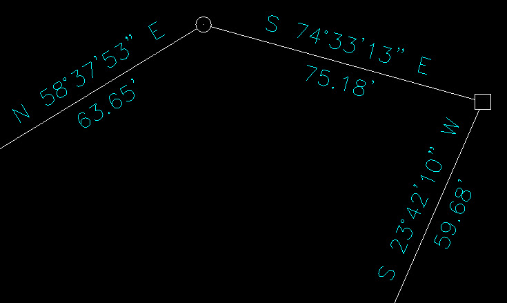
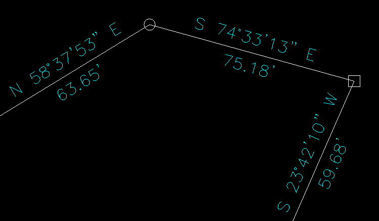
Problem: Lines or polylines of a boundary show up inside your open property corner symbols. See the image below for an example:

Property Corner Symbols without AutoCAD Wipeout


The additional problem is that, if you trim the lines inside the symbols to make it look cleaner, you’re actually modifying the length of property lines so the distances from corner-to-corner are no longer accurate.

Here’s an alternative: You can download a modified set of Carlson’s point symbols that include a “wipeout” entity that hides the lines behind/underneath the open symbols instead of trimming them and changing the length of the lines. Using the new set of symbols, the same property lines and symbols look like those in the image below (notice that the distances of linework are unchanged):

Property Corner Symbols with AutoCAD Wipeout


How to do this?

Here is the knowledge base article on Carlson’s website that includes a ZIP file with the new symbol DWG files and instructions on where the files must be saved.


Did You Know… About Carlson’s Export to KMZ (Google Earth) Command?

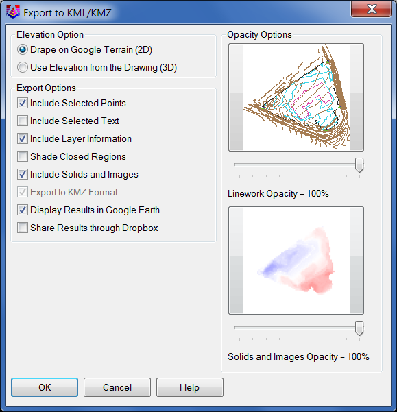
Carlson Software gives you the ability to export drawing entities directly to the Google Earth application or, alternatively, to a .kml or .kmz file that can be opened in Google Earth. At this time Carlson supports the export of points, polylines, text, solids, images, lines and arcs to Google Earth or .kml/.kmz files.

In Carlson 2014 they have also included the option of sending the Google Earth file directly to a Dropbox account for sharing with clients or other project team members.

The Export to Google Earth command is found in the File menu in all Carlson desktop programs.

Export to KMZ file


Did you know… About the Flatten Command?

FLATTEN is an Express Tools command in AutoCAD and a standard command in IntelliCAD. It allows you to quickly convert 3d objects to a 0-elevation, flat version of itself.

Most of us in the civil/survey world have gotten frustrated when we’ve received a drawing from someone who used lines more than polylines and apparently snapped to everything in the drawing that had an elevation! The result is that you have lines drawn on a slope and with which it’s nearly impossible to inverse distances or even perform simple drafting commands.

So, next time that happens, try the FLATTEN command and see if that helps get things back where they’re supposed to be!


Did you know… about all the different selection methods in CAD?

Anyone who has used AutoCAD or IntelliCAD for any period of time will be familiar with a few of the selection methods available to you during editing commands… although you may not know the “official” name of the method.

When your Command: line prompted reads “Select Entities:”, you can use the following methods to add entities to the selection set:

A Single selection is when you use a “Pickbox” to select one entity at a time.

An Implied Window selection is when you drag a rectangular area, from left to right, around the entities to be selected. This method will select any entities that are fully enclosed within the area. To force a Window selection, you can also type “W” at the Command: line when prompted to “Select Entities:”. Window selections are indicated by the solid outline of the rectangle and a color shading within the rectangular area.

An Implied Crossing selection is when you drag a rectangular area, from right to left, around or across the entities to be selected. This method will select any entities that are fully enclosed or touch (cross…) the outline of the rectangle. To force a Crossing selection, you can also type “C” at the Command: line when prompted to “Select Entities:”. Crossing selections are indicated by the dotted or dashed outline of the rectangle and a color shading within the rectangular area.

So, these are the ones you probably know about. But, what about these?

Again, when prompted to “Select Entities:”, you can do any of the following:

Hold the SHIFT-key down while selecting objects using Single, Implied Window or Implied Crossing selection methods will un-select any objects previously selected.

Type “P” at the Command: line to use the Previous selection method. This method will automatically select the same objects that had been selected for the most recent editing command. This obviously doesn’t work if the Previous selection set has been ERASEd from the drawing.

Type “L” at the Command: line to use the Last selection method. This method will automatically select the entity most recently added to the drawing. The entity must also be visible on the drawing screen in order to be selected.

Type “ALL” at the Command: line to use the All selection method. This method will automatically select all entities visible in the current space.

Type “F” at the Command: line to use the Fence selection method. This method allows you to drag a line (by picking points) across the entities to be selected. When picking the points for the Fence, the sketched line is dashed or dotted. This method is similar to a Crossing selection as it will select anything that touches the Fence.

Type “WP” at the Command: line to use the Window Polygon selection method. This method allows you to sketch an irregularly shaped area (by picking points) around the entities you wish to select.  Any entities that are completely inside of the non-rectangular area will be selected. This is simply a non-rectangular version of the Window selection method. Window Polygon selection areas are indicated by the solid outline  and color shading of the irregularly shaped area.

Type “CP” at the Command: line to use the Crossing Polygon selection method. This method allows you to sketch an irregularly shaped area (by picking points) around or across the entities you wish to select. Any entities that are completely inside of the non-rectangular area or touching its outline will be selected. This is simply a non-rectangular version of the Crossing selection method. Crossing Polygon selection areas are indicated by the dashed or dotted outline  and color shading of the irregularly shaped area.

If you have a complex selection set and need to un-select several entities, you may find it impractical (and frustrating) trying to un-select everything by using SHIFT+<select> to do so.

Another way to un-select a bunch of entities is to use the Remove selection mode. When prompted to “Select Entities:” at your Command: line, type “R” to change your Command: line prompt to “Remove Entities:”. Now, any entities you select, using any method, will be Removed from the selection set. You do not have to hold SHIFT and you can use Fence, Last, Window Polygon, etc. to remove those items.

After Removing entities from the selection set, type “A” at the Command: line to return to the Add selection mode. This changes the Command: line prompt back to “Select Entities:” and you will once again be able to Add objects to the selection set.


Did you know… about the new rainfall libraries in Carlson Hydrology 2013?

With the 2013 release of Carlson Hydrology, Carlson is shipping complete rainfall libraries for the following cities in North Carolina:

  • Asheville
  • Cary
  • Chapel Hill
  • Charlotte
  • Concord
  • Durham
  • Fayetteville
  • Gastonia
  • Greensboro
  • Greenville
  • High Point
  • Jacksonville
  • Raleigh
  • Rocky Mount
  • Wilmington

The rainfall information has been compiled from the precipitation intensity charts available from The National Weather Service.

To load and access these files:

  • Switch to your Carlson Hydrology menu
  • Go to Network > Sewer Network Libraries > Rainfall Library
  • Pick the Load button
  • Browse to C:Carlson ProjectsSettingsNorth Carolina


Did you know… About the Change Space Command?

Some of us are old enough to remember life without the CHSPACE command… and what a great addition it was when the command was finally introduced to AutoCAD several years ago. And, with the release of IntelliCAD 7, it’s now in that program as well.

CHSPACE is a command that allows you to move one or more entities from Model Space to Paper Space (or vice versa) very easily. In AutoCAD, the operative word there is “MOVE”. You have to be a little careful because the command does exactly that: It MOVES it from paper to model or from model to paper. In IntelliCAD, you are given the option of COPYing the selected entities from one space to the other.

The command actually does more than just move or copy selected entities, it also scales the entities by the viewport scale so they’re correct size-wise. For instance, let’s say that you have a drawing in model space that’s been rotated so that it more easily fits on a sheet of paper. Also in model space, you’ve inserted a North arrow. And, in paper space/layout view, you have inserted a title block at a scale of 1:1 (18″ x 24″, etc.). Inside of the title block, you’ve created a viewport you’ve scaled to 1″=40′.

For drafting purposes, it’s desirable to have the North arrow in paper space to that it can be moved around and positioned outside the viewport. If you’re in AutoCAD, the first step is to make a copy of the North arrow. If you’re using IntelliCAD, this step isn’t necessary. Then, while in paper space/layout view, double-click inside the viewport to make it active. Type CHSPACE at the Command: line. Follow the various prompts within the command and Voila! Your North arrow is now in paper space and it’s been scaled down by 40 times so that it fits properly on your title block.


Did you know… that you can print your CTB files?

Several years ago when I started my business, my first contract was as an outside CAD manager for a civil & land planning firm. In trying to document their pen weights, screening, etc. I found a utility available on Autodesk’s website that allowed me to export all the values in a CTB file to a .csv file that could be opened (and printed) with Excel.

Here is the old Autodesk Knowledge Base article – it still works for anyone using AutoCAD-based programs version 2007-2008.

Unfortunately, I haven’t been able to find a more current version of this utility until recently. Govert’s Tools has a program called PlotStyleViewer. You can download it here.

In his words,

This inspired me to create a CTB/STB view/print application that works completely independent of AutoCAD and Autodesk tools! The program consists of just one executable file, there are no other exe’s or dll’s needed. It should work with CTB’s/STB’s from AutoCAD 2000 upto the latest version. The purpose of this tool is that you can view CTB’s, print them and save as text file that you can open in Excel etc.

It’s a handy little utility and doesn’t seem to be limited to a particular version. Hope you get as much use out of it as I do.


Did you know… About DWG Convert & True View?

As most everyone knows, every 3 years Autodesk ruins a perfectly good DWG format by introducing a new one…

With the 2013 version of the Autodesk products now released, anyone using a version of AutoCAD older than 2013 can expect to start receiving 2013 .dwg files that they can’t access because its an incompatible version. This is where the DWG Convert function inside of DWG TrueView can be a lifesaver.

DWG TrueView is FREE utility available from Autodesk. They release a new version of this program every year, just like their other products.

With the True Convert utility you can convert any newer version DWG or DXF to any earlier version. I’d recommend you enable the option that creates a .bak file with the original just in case you need it later.

Inside the True Convert utility you can also enable several other options that will run routines such as Audit, Purge, XREF Binding, etc. during the convert process.

You can download DWG True View 2013 here.


Did you know… about DWG to PDF?

Since I have to send so many files to different people in PDF format, I purchased Adobe Acrobat several years ago. Once installed, “Adobe PDF” shows up in my list of available printers just like my HP or Brother printers do. There are also several other programs available online that allow you to create a PDF printer. Although I’ve never used them, I’ve heard good things about CutePDF and Sourceforge PDF Creator and I’ve used Win2PDF in the past. Each of these have a free version but you may end up getting a watermark or footer or 2nd page that states you’re using a Free copy.

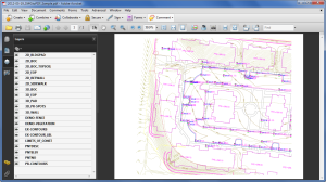
Any of these can be installed and will be shown as an available printer in the Plot dialog box of AutoCAD or IntelliCAD. Several years ago AutoCAD started including a DWG to PDF.pc3 file allowing AutoCAD users to use that tool rather than having to purchase a separate application to create PDFs. One advantage of using the DWG to PDF is that there is an option to save all the layers used in the DWG with the PDF file. With this setting enabled, anyone viewing the PDF through a PDF viewer has the ability to make one or more layers invisible. See the image below for an example:

Drawing Layers in PDF File

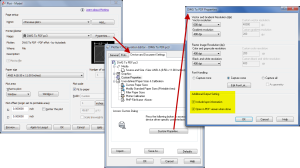
While this is a neat feature, you might not always want your list of layers to transmit with your PDF. If not, it’s easy enough to change the option. In the Plot dialog, set the current plotter to DWG to PDF.pc3 and then pick the Properties button to the right. Under the Device and Document Settings tab, you can change several options such as available paper sizes. You can also select the “Custom Properties” item in the tree for special options that are unique to the “printer”. You can see in the image below that this is where you can find the option for whether or not to “Include layer information”.