That CAD Girl – April 2012 Newsletter

In case you missed it, here is our April 2012 Newsletter


Thank you to the Richmond AutoCAD Manifest (RAM)

I’d like to thank Art Thomas and the Richmond Virginia AutoCAD User Group for inviting Jeremy and me to demonstrate Carlson Software and data collection last night. Our hour-and-a-half long presentation covered the basic tools and Survey, Civil and GIS specific features of the Carlson products.

The RAM User Group has been active for 20+ years and has a lot to offer CAD users in the central Virginia area. Their meetings are usually on the 3rd Wednesday of each month and start after work at 5:30. If you’re based in the Richmond area, I’d highly recommend that you join up with them.


Carlson SurvCE and Field to Finish Training with Jeremy Taylor PLS

Join us on Monday, May 7th when Jeremy and I will be presenting this part-field and part-office training with SurvCE.

Topics for the day will include:

  • Set up and configuration of SurvCE with your equipment
  • Managing data files and import/export options between the field and the office
  • Field collection for boundary, features and topo including GIS collection
  • Working with the Map Menu to import and export .dwg, .dgn, .mxd and shapefiles
  • Stakeout techniques
  • Overview of Field to Finish


Register Here

SurvCE and Field to Finish Training Announcement


Did you know… About Coordinate Display Toggles?

Did you know that, when you’re in AutoCAD or IntelliCAD, you have a couple of different options when it comes to displaying the coordinate position of your crosshairs?

For instance, when you’re NOT in a command, you have two options for displaying the coordinate position of your crosshairs as it moves across your screen: On or Off. If the coordinate display is toggled ON, then the X, Y and Z position (rectangular coordinates) of your crosshairs are displayed and if it’s OFF, then the X, Y and Z display is frozen and doesn’t update as your mouse moves.

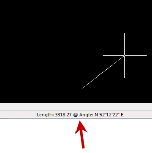
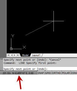
However, if you are currently in a command that requires two points be picked to specify an angle and distance (commands such as Line or Move, etc), you have a 3rd coordinate display available to you: polar coordinates. Unlike rectangular coordinates that display X, Y and Z position, polar coordinates report a distance and angle from the original point. For instance, when you start the Line command you can toggle the coordinate display so that rectangular coordinates are ON or OFF. But, after picking the first point of the line, you can toggle the coordinate display so that rectangular coordinates are ON, rectangular coordinates are OFF or that polar coordinates are ON.

The image below on the left shows the polar coordinate display in AutoCAD and the IntelliCAD version is shown below on the right:

IntelllliCAD Coordinate DisplayAutoCAD Coordinate Display


To toggle the coordinate display in newer versions of AutoCAD (since 2009?) double-click on the coordinate display. In older versions of AutoCAD and in IntelliCAD, the F6 button toggles the display.


Did you know… How easy it is to spruce up your dimensions?

Anyone who has worked with AutoCAD for any length of time can usually create a standard dimension object. However, if you pay close attention to two items in the Object Properties dialog box, you can get very creative with the way simple dimensions are displayed.

For instance, in the image just below, you can see that there are two Object Properties items highlighted in yellow. One is the “Measurement” and the other is the “Text override”. The Measurement is the measured distance between the dimension definition points (DEFPOINTS) and is read-only. You can also see that the current value for Text override is “< >”. Whenever the less-than and greater-than signs are shown as the Text override value, the Measurement will be substituted for the symbols when displayed in the drawing.

Dimension Example

To add just a little more detail to the dimension, you can add descriptive text before or after the “< >” in Text override as shown in the next example below. As long as you keep the “< >”, the correct measured distance will always be displayed as part of the dimension text:

Dimension Example 2And, making it fancier… In the example below, I have added a “P” between < > and “9 SPACES”. This is like pressing Enter to go to a second line and has the effect of stacking two lines of text above the dimension line:

Dimension Example 3

And, finally, one more option. Rather than entering “P”, if you enter “X” as part of your Text override, you will stack the text partially above and partially below the dimension line.

Dimension Example 4The “P” and “X” modifiers can also be used in combination to create 3 or more lines of text and allowing you to control how many lines appear above and how many appear below the dimension line.


Carlson SurvPC Data Collection Now Works with Esri & MicroStation Files

With a post to their blog last night, Bruce Carlson announced that Carlson SurvPC data collection software (Windows version of SurvCE) can now view and write directly to the Esri .mxd and Bentley Microstation.dgn file formats. This is pretty exciting stuff for both survey field crews and those who wish to design-on-the-fly from the field.

Read more here


Tips & Tricks for Setting Points in Carlson – Webinar

Yeah, you know all of them already… Unless you don’t!

Carlson has a lot of great tools that are available for setting points but some of them are a little hidden. I will be covering some features in Carlson Survey and Carlson Civil that will, hopefully, help you increase your productivity.

Register Now! Wednesday, February 29th – Tips & Tricks for Setting Points in Carlson


Carlson Boot Camp Training in New Jersey – Approved for PDH Credit

I just received word from the NJ State Board of Professional Engineers & Land Surveyors that our Woodbridge classes will be accepted for continuing education credit. Our full list of upcoming classes in Columbus Ohio, Chicago Illinois and Upstate South Carolina can be found here.

Boot Camp! Carlson Survey & Field to Finish – April 10, 2012 – Woodbridge, NJ

Boot Camp! Surface Modeling – April 11, 2012 – Woodbridge, NJ


Did you know… About Temporary Overrides?

There are others, but my two favorites are:

  • Holding Shift while in a Draw or Modify command allows you to override your current ORTHO setting.

So, if you’re drawing a line and ORTHO is Off, holding Shift will temporarily turn ORTHO On. As soon as you let up on the Shift key, ORTHO will be Off again. Likewise, if ORTHO is On, holding Shift will temporarily turn it Off.

  • Holding Shift while in the Fillet command allows you to override your current Radius setting and apply a Radius of 0.0 between the two selected entities.

So, if you’re drawing a parking lot and find yourself constantly changing your Fillet Radius between 0.0 and another value to create both sharp and rounded corners, leave the Radius set to something other than 0.0 and just hold Shift when you pick the two entities to apply a 0.0 Radius.


These Temporary Overrides are available in all “flavors” of AutoCAD as well as in IntelliCAD.


Job Opening – Piedmont Triad Region, North Carolina

One of my clients has an immediate opening for a CAD/GIS Technician.

Click here for a full job description

If you are interested, please submit your resume plus a copy of this job description to [email protected] and I will forward it along.