Google Earth/KMZ Overlays: Flood Zones, State Plane and UTM Zones

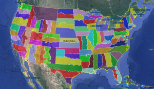
Google Earth KMZ file of State Plane NAD 83 Zones


A CAD/Carlson Software buddy – Dent Cermak – passed along a response from FEMA to questions regarding the features available on FIRM maps. The FEMA rep recommended using National Flood Hazard Layer data to view flood data overlays on aerial, street and other imagery. The NFHL data is available  via an online viewer here: http://fema.maps.arcgis.com/home/webmap/viewer.html?webmap=cbe088e7c8704464aa0fc34eb99e7f30.

Another way to access the NFHL data is to download it as a KMZ file that can be opened in Google Earth: https://hazards.fema.gov/femaportal/wps/portal/NFHLWMSkmzdownload.

So, I thought this was pretty cool and when I asked for Dent’s permission to share on my website, he passed along a couple more .kmz files that were even more cool! These are courtesy of Ladd Nelson at Carlson Software.

If you have Google Earth installed on your computer, you only have to double-click to open these files in Google Earth.

KMZ file with US State Plane NAD83 Zones overlay – ZIP file

KMZ file with UTM Zones overlay – ZIP file


Carlson Tip: Using Carlson Software? Here’s what to look for in a new computer

Problem: You’re running Carlson Software and need a new computer… What do you need and how much do you need to spend?

The shortest answer is to follow this link to Carlson’s website: Carlson Software System Requirements

The short answer, if you’re running one of Carlson Software’s programs with embedded AutoCAD/OEM or on top of a full AutoCAD, is to follow Autodesk’s system recommendations/requirements for the platform. The Carlson part that runs on top has a relatively light footprint compared to the AutoCAD underneath, so you’ll need to make sure your new computer can run the AutoCAD-engine and the rest will be fine.

Carlson running on top of IntelliCAD also has a pretty light footprint compared to anything developed by Autodesk. Unless your drawings are loaded with a lot of layout tabs and viewports, there’s a very good chance an off-the-shelf computer from Best Buy or Wal-Mart will be sufficient.

Since I’m a self-described hardware “dummy” and that’s not the most technical answer, I asked Leonid Entov, the Assistant Director of Office Software Development at Carlson Software, for a better, layman’s-terms answer:

In one sentence, I would summarize recommended computer as i7 processor, discrete graphics (not integrated), preferably Nvidia chip since we seen more of driver issues with ATI/AMD and 8 gb of RAM (Windows tends to eat too much of 4gb these days). You do not have to go to gaming computers, something like this would be possible to find in $700+ range in laptops.

Since there are too many CPUs on the market, this site helps to compare individual CPUs : http://www.cpubenchmark.net/cpu_list.php

Thanks Leonid!

And I can’t post this without reminding everyone that Carlson’s tech support team is great and will be happy to answer any specific questions you have. Their tech support is free, all the time, whether you’re using a 30-day trial or if you’ve already purchased and whether you’re using the most current version of the software or one that’s 10 years old.

Click here to request a 30-day trial of Carlson Software


Did you know… about all the different selection methods in CAD?

Anyone who has used AutoCAD or IntelliCAD for any period of time will be familiar with a few of the selection methods available to you during editing commands… although you may not know the “official” name of the method.

When your Command: line prompted reads “Select Entities:”, you can use the following methods to add entities to the selection set:

A Single selection is when you use a “Pickbox” to select one entity at a time.

An Implied Window selection is when you drag a rectangular area, from left to right, around the entities to be selected. This method will select any entities that are fully enclosed within the area. To force a Window selection, you can also type “W” at the Command: line when prompted to “Select Entities:”. Window selections are indicated by the solid outline of the rectangle and a color shading within the rectangular area.

An Implied Crossing selection is when you drag a rectangular area, from right to left, around or across the entities to be selected. This method will select any entities that are fully enclosed or touch (cross…) the outline of the rectangle. To force a Crossing selection, you can also type “C” at the Command: line when prompted to “Select Entities:”. Crossing selections are indicated by the dotted or dashed outline of the rectangle and a color shading within the rectangular area.

So, these are the ones you probably know about. But, what about these?

Again, when prompted to “Select Entities:”, you can do any of the following:

Hold the SHIFT-key down while selecting objects using Single, Implied Window or Implied Crossing selection methods will un-select any objects previously selected.

Type “P” at the Command: line to use the Previous selection method. This method will automatically select the same objects that had been selected for the most recent editing command. This obviously doesn’t work if the Previous selection set has been ERASEd from the drawing.

Type “L” at the Command: line to use the Last selection method. This method will automatically select the entity most recently added to the drawing. The entity must also be visible on the drawing screen in order to be selected.

Type “ALL” at the Command: line to use the All selection method. This method will automatically select all entities visible in the current space.

Type “F” at the Command: line to use the Fence selection method. This method allows you to drag a line (by picking points) across the entities to be selected. When picking the points for the Fence, the sketched line is dashed or dotted. This method is similar to a Crossing selection as it will select anything that touches the Fence.

Type “WP” at the Command: line to use the Window Polygon selection method. This method allows you to sketch an irregularly shaped area (by picking points) around the entities you wish to select.  Any entities that are completely inside of the non-rectangular area will be selected. This is simply a non-rectangular version of the Window selection method. Window Polygon selection areas are indicated by the solid outline  and color shading of the irregularly shaped area.

Type “CP” at the Command: line to use the Crossing Polygon selection method. This method allows you to sketch an irregularly shaped area (by picking points) around or across the entities you wish to select. Any entities that are completely inside of the non-rectangular area or touching its outline will be selected. This is simply a non-rectangular version of the Crossing selection method. Crossing Polygon selection areas are indicated by the dashed or dotted outline  and color shading of the irregularly shaped area.

If you have a complex selection set and need to un-select several entities, you may find it impractical (and frustrating) trying to un-select everything by using SHIFT+<select> to do so.

Another way to un-select a bunch of entities is to use the Remove selection mode. When prompted to “Select Entities:” at your Command: line, type “R” to change your Command: line prompt to “Remove Entities:”. Now, any entities you select, using any method, will be Removed from the selection set. You do not have to hold SHIFT and you can use Fence, Last, Window Polygon, etc. to remove those items.

After Removing entities from the selection set, type “A” at the Command: line to return to the Add selection mode. This changes the Command: line prompt back to “Select Entities:” and you will once again be able to Add objects to the selection set.


Did you know… About Coordinate Display Toggles?

Did you know that, when you’re in AutoCAD or IntelliCAD, you have a couple of different options when it comes to displaying the coordinate position of your crosshairs?

For instance, when you’re NOT in a command, you have two options for displaying the coordinate position of your crosshairs as it moves across your screen: On or Off. If the coordinate display is toggled ON, then the X, Y and Z position (rectangular coordinates) of your crosshairs are displayed and if it’s OFF, then the X, Y and Z display is frozen and doesn’t update as your mouse moves.

However, if you are currently in a command that requires two points be picked to specify an angle and distance (commands such as Line or Move, etc), you have a 3rd coordinate display available to you: polar coordinates. Unlike rectangular coordinates that display X, Y and Z position, polar coordinates report a distance and angle from the original point. For instance, when you start the Line command you can toggle the coordinate display so that rectangular coordinates are ON or OFF. But, after picking the first point of the line, you can toggle the coordinate display so that rectangular coordinates are ON, rectangular coordinates are OFF or that polar coordinates are ON.

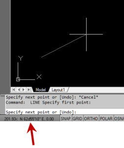
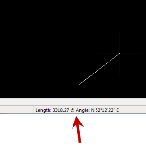
The image below on the left shows the polar coordinate display in AutoCAD and the IntelliCAD version is shown below on the right:

IntelllliCAD Coordinate DisplayAutoCAD Coordinate Display


To toggle the coordinate display in newer versions of AutoCAD (since 2009?) double-click on the coordinate display. In older versions of AutoCAD and in IntelliCAD, the F6 button toggles the display.


Did you know… How easy it is to spruce up your dimensions?

Anyone who has worked with AutoCAD for any length of time can usually create a standard dimension object. However, if you pay close attention to two items in the Object Properties dialog box, you can get very creative with the way simple dimensions are displayed.

For instance, in the image just below, you can see that there are two Object Properties items highlighted in yellow. One is the “Measurement” and the other is the “Text override”. The Measurement is the measured distance between the dimension definition points (DEFPOINTS) and is read-only. You can also see that the current value for Text override is “< >”. Whenever the less-than and greater-than signs are shown as the Text override value, the Measurement will be substituted for the symbols when displayed in the drawing.

Dimension Example

To add just a little more detail to the dimension, you can add descriptive text before or after the “< >” in Text override as shown in the next example below. As long as you keep the “< >”, the correct measured distance will always be displayed as part of the dimension text:

Dimension Example 2And, making it fancier… In the example below, I have added a “P” between < > and “9 SPACES”. This is like pressing Enter to go to a second line and has the effect of stacking two lines of text above the dimension line:

Dimension Example 3

And, finally, one more option. Rather than entering “P”, if you enter “X” as part of your Text override, you will stack the text partially above and partially below the dimension line.

Dimension Example 4The “P” and “X” modifiers can also be used in combination to create 3 or more lines of text and allowing you to control how many lines appear above and how many appear below the dimension line.