If You’re Not Using LandXML – You Should Be (yes, all of you!)

This is a badly needed webinar… I don’t think I’ve done one specifically on this topic before and, for the life of me, I don’t know why. For years I’ve been speaking to large groups at conferences and trade shows and it never ceases to amaze me how few people know the benefit of using LandXML files!

landxmlorg

This will be a little different from my regularly scheduled webinars because it’s FREE to everyone, there is no purchase required and the material presented will apply to everyone regardless of the civil/survey/construction software you use. Whether you know it or not, you’ve probably got everything you need already in your current software – you just need to put it to use.

So, what prompted me to finally schedule it? These poor people still using Land Desktop or Eagle Point calling me in a panic because their hard drives have finally crashed and they can’t get the old software installed on newer Windows machines. Don’t get me wrong, I don’t fault anyone for hanging on to something that works but the ones who call me never realized they had the tools to protect themselves and salvage years of project data all along.

You can register here (no strings attached – promise!) or keep reading for the full announcement…

Please join me in this free webinar while I explain the benefits of, and how to use, LandXML-formatted files to share and archive project-related data files regardless of the manufacturer or version of software you and other team members use.

Although many people do not realize it, LandXML is a tool that’s most likely in your hands now and won’t require any additional purchase.

This webinar is a MUST SEE for anyone still using Land Desktop, Eagle Point or other program that has been retired because it is increasingly difficult, if not impossible, to install these programs on newer computers.

The information provided in this webinar will apply equally to users of Carlson Software, Land Desktop, Civil 3d, TerraModel, Eagle Point and practically any other software for surveyors, engineers or contractors (including machine control systems).
==============
This webinar will last approximately 1 hour and there will be time for questions at the end.

Click here to register for the webinar now


Carlson Software Product Updates 7/1/2015

cad03-13

It’s been about a month since Carlson released the latest build of their 2015 desktop products so I figured it was time to post them here for easy access…

Download 6/9/2015 build here  This link takes you to the page where you can download a full version of the software or updates to bring your 2015 up to date.

Updates to the following desktop modules are included in this file: Survey, Civil, Hydrology, GIS, Basic Mining, Geology, Underground Mining, Surface Mining, Natural Regrade, Field, CADnet, GeoTech, Trench, Construction and Point Clouds. This can be installed on AutoCAD 2007-2015 or with included Intellicad 8.0. AutoCAD 2010-2015 releases are supported on 64-bit Windows. Your Carlson 2015 Serial number is required for installation.

Carlson 2016 will be released before too long. If you’ve let your maintenance contract expire (accidentally or on purpose!), now would be a good time to get back on board. If you renew before 2016 is released, it’ll be cheaper and you’ll receive 2015 now and 2016 when it’s released. Win! Win! Win!

You can request pricing for new licenses or upgrades here

And, while I’m at it, here are the links to download the latest updates for other programs:

Survey 2015 OEM (embedded AutoCAD 2015) – Download the 5/8/2015 build here

Takeoff T8 OEM (embedded AutoCAD 2015) – Download the 3/23/2015 build here

SurvCE 4.0 – Download the 5/15/2015 build here

SurvPC 4.05 – Download the 5/15/2015 build here


Thank You for A Great 2014!

That CAD Girl #1 in Sales of Carlson SoftwareCarlson Software recently let me know that – for the 5th year in a row!! – That CAD Girl was #1 in sales of their desktop products!

I owe a huge “Thank You” to my current customers who come back to me for additional purchases and for passing my name along to others because I know I couldn’t do this without you.

The best compliments I receive are your referrals and I look forward to working with you in 2015 and beyond.


Carlson Survey 2015 with Embedded AutoCAD has been released

Carlson Survey 2015


MAYSVILLE, Ky., U.S.A. (August 13, 2014)—  Carlson Survey 2015 OEM is an easy-to-use, intuitive software. Its newest update provides upgrades to the 3D viewer that allows users to apply textures, animation, surface updates, even record movies and import Sketch-Up objects. The software’s popular field-to-finish feature has also been enhanced for 2015 to allow surveyors to do coding on pipe networks that then allows them to build a network of pipes.

Together with Carlson Survey 2015 version, which works on AutoCAD® versions 2007 to 2015 and comes with the improved IntelliCAD® 8.0 built-in, Carlson Survey OEM is the number one office software solution for surveyors in the United States.

Read the rest of the press release

Request a 30-day trial

Request a live demonstration

Request a custom proposal

See these products in our Online Store


Job Opening – Piedmont Triad Region, North Carolina

One of my clients has an immediate opening for a CAD/GIS Technician.

Click here for a full job description

If you are interested, please submit your resume plus a copy of this job description to [email protected] and I will forward it along.


IntelliCAD Webinar – Do Over

Last week I presented a webinar sponsored by Carlson Software on the topic “Updates and Overview of IntelliCAD 7”. Unfortunately we had some technical difficulties and didn’t get a complete recording to post to the Movies collection on Carlson’s website.

For those who are interested, we will be re-doing the webinar on Thursday, March 29th. By that time we expect to have additional updates and improvements to announce.

Keep an eye on this site to register for the next IntelliCAD webinar

You can register for these future webinars by clicking the link below:


Did you know… About the Upright flag for linetypes?

I didn’t until this weekend.

While working on a new Picks and Clicks article for Professional Surveyor magazine I stumbled on something incredibly handy. This setting keeps text that’s inserted into a linetype in an Upright position rather than allowing it to be upside-down. 

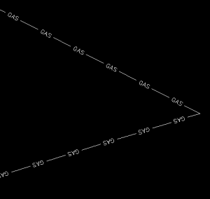
Notice the polyline in the picture below. The top segment (drawn from left to right) has the text upright but the bottom segment (drawn from right to left) shows the text upside-down.


text is upside-down in linetype

The reason this happens is because of the definition of the “GAS_LINE” linetype in the acad.lin file.

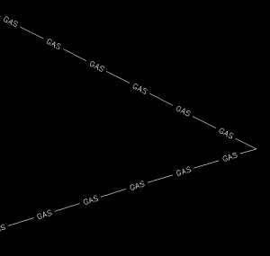
The R=0.0 parameter formats the linetype text so that it aligns with the line segment. Therefore, whether text is upright or upside-down depends on the direction the line is drawn. However, if you simply change the R=0.0 to U=0.0, the polyline displays like this:


text is upright in the linetype

Notice the text is now upright in both segments. Using the U in the linetype definition sets the “Upright” flag. Setting it to 0.0 keeps it Upright relative to the line. I played around with it a bit and, unfortunately, it doesn’t seem to help much when rotating with DVIEW or UCS. But, when you’re working in world coordinates, this is a great tool.

To my knowledge this is a recently added enhancement to AutoCAD – but I thought it was cool enough to put up here!

My next column in Professional Surveyor will be… Surprise! Standardizing Linetypes! I’ll post a link here when it’s posted on their site. Follow this link to see if you are eligible for a free subscription to the print magazine: Subscribe to Professional Surveyor magazine.


Picks and Clicks: The Key to Standardizing Annotation in CAD Files

This article originally appeared in the June 2011  issue of Professional Surveyor magazine.

Part 1

The issue of CAD standards has long been one of my pet projects when working with clients. It’s the universal problem, as folks from every office confess that CAD standardization is either “non-existent” or, at least, “could be better.”

In my experience, the single most-intimidating aspect to developing a CAD standard is deciding how to standardize annotation in order to accommodate the multiple scale factors used in a typical plan set. Other types of sheets surveyors and civil engineers may have to produce are:

  • a cover sheet (at 1:1 or no scale),
  • one or more project or phase site plan sheet (at 1:50, 1:100, 1:500, 1:1000, etc.),
  • plan and profile sheets (at 1:30, 1:50, etc.), and
  • detail sheets (at 1:1 or no scale).

It’s not an easy issue to resolve, and CAD programs seem to vary from bad to worse in their ability to manage multiple scales within a single CAD file.

Some of the information provided here is very basic, but in my experience even long-time CAD users struggle a bit with the “under-the-hood” details about annotation sizing. So, that being said, where should you start?

Determine the Plotted Size, Plotted Height, Plotted Distance … of Everything

The most important first step when developing a CAD standard for annotation is to determine the desired plotted size of annotation entities. And, when we discuss annotation, we must remember that this encompasses more than just text; it also means linetype patterns and dimension styles.

Here are several sample questions to ask when developing a CAD standard for annotation:

  • When plotted, what is the height (in inches) of the text displaying:

– the project title in the title block?

– the road name?

– contour labels?

– 
property line bearings and distances?

  • When plotted, how far off the property line (in inches) should the bearing and distance label be placed?
  • When plotted, what is the distance (in inches) between labels along a contour?
  • When plotted, what is the length (in inches) of the arrowheads at the end of dimension objects?
  • When plotted, what is the distance (in inches) that the extension line extends beyond the dimension line?
  • When plotted, what is the length (in inches) of the dashes and gaps in the linetype used to show existing contours?

Overwhelmed yet? Don’t be. Once you commit to the size or height of a few entities, the rest come fairly easily just because you know that you want one entity a little smaller or a little bigger than another.

The remainder of this column covers the issue of standardizing text sizes in your CAD files. Future columns will cover the other questions relating to linetypes and dimension styles in much more detail.

Standardizing Text Sizes and Placement
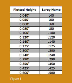
Although text height can be set to any desired value, the most commonly used height for plotted text in civil/survey drawings is 0.08”. There are several other standard text styles (corresponding to the height of the plotted text), known as “Leroy,” that have been adopted from the days of hand and technical lettering. Even though the “Leroy” text style usually has a Simplex font, the naming convention is widely accepted to describe text of a specific height regardless of its font.  For instance, L80 text refers to a Leroy style text that plots 0.08” high; L100 is Leroy with a plot height of 0.10”; and L200 is Leroy with a plot height of 0.20”. Other standard heights and style names are shown in figure 1.

L80, or text that plots 0.08” high, is generally used for basic text such as bearings and distances, contour labels, and notes. For more prominent text such as road names or parcel numbers an L150, or text plotting 0.15”, may be used.

You may be saying, “Yeah, that’s great and all, but when I enter text it asks me for the height of the text to be placed in the drawing, not its plotted height.” If you use the generic commands for placing text, that is true. However, most civil/survey programs have specialized commands for labeling that also take into account a horizontal scale that you specify independently for each drawing.

For instance, in Carlson Software or Civil 3D, you can specify program defaults so that bearing and distance labels always have a plotted height of 0.08”. Then, as each new drawing is started, you set its horizontal scale. For a drawing with a horizontal scale set to 1”=50’, the bearing and distance labels will be placed in the drawing at a height of 4.0’ (0.08 x 50 = 4.0). For a drawing with a horizontal scale set to 1”=100’, the bearing and distance labels will be placed in the drawing at a height of 8.0’ (0.08 x 100 = 8.0). The plotted height never changes.

Consider what a written standard for annotation would look like if we did not base the standard on the plotted size but on the actual drawing size of text…

  • In all 50-scale drawings, bearing and distance labels shall be placed in the drawing at 4.0’ high.
  • In all 100-scale drawings, bearing and distance labels shall be placed in the drawing 8.0’ high.
  • In all 50-scale drawings, all property corner labels shall be placed in the drawing 3.0’ high.
  • In all 100-scale drawings, all property corner labels shall be placed in the drawing 6.0’ high.
  • Unless otherwise specified, all other text in a 50-scale drawing shall be placed in the drawing 4.0’ high.
  • Unless otherwise specified, all other text in a 100-scale drawing shall be placed in the drawing 8.0’ high.

Now, with the understanding that all annotation sizes must be scaled by the horizontal scale, we can simply say:

  • All road names shall be L150.
  • All property corner labels shall be L60.
  • Unless otherwise specified, all other text shall be L80.

As you can see, because the text sizes refer to a plotted height, it makes the writing of CAD standards for annotation remarkably easier.

It is also important to note that, when placing text in a drawing, parameters other than text height can be adjusted to get the desired look. One of these 
parameters is the distance a label is placed above or below the line it labels.  Figure 2 shows a clip of the Annotate Defaults dialog box in Carlson Survey 2011.

The text height is specified using the “Text Size Scaler” value, and the distance that text is offset from the line it labels is specified by the “Text Offset Scaler.” Both of these values are “plotted” distances in inches. You can also see the horizontal scale setting for the drawing. Once plotted, text placed using these settings will be 0.08” high, and it will be positioned 0.04” off the line. A good rule of thumb is to set the offset value at one half the text height.

Another example of an annotation standard that can be associated with a plotted distance is how far apart to place elevation labels along a contour. Rather than specifying that contour labels are “300’ apart in a 50-scale drawing” or “600’ in a 100-scale drawing,” your standard should state that: On the plotted sheet, contour labels shall be shown at 6” intervals along each index contour.

I hope this information has provided a good kick-start toward your CAD standardization goals and helps get you thinking in plot sizes rather than drawing sizes. As noted above, future columns will focus on other supposed standardization nightmares such as dimension styles and will also touch on some specifics of the different CAD programs. Please don’t hesitate to contact me if you have questions. I hope your summer is off to a great start!

This article originally appeared in the June 2011 issue of Professional Surveyor magazine.


What is Carlson up to?

This is a good article about Bruce Carlson and where Carlson Software is planning to go in the future…

Independence All the Way

Originally posted on Carlson Connection by Jennifer Dibona


Online Training – Friend or Foe?

With the economy what it is and everyone trying to get as much bang for their buck as possible, I’m finding that online training for your CAD software programs is an increasingly popular and cost effective option.

Although this post describes my personal approach and may be different considering your trainer, hopefully it will answer some of your questions about online training and will encourage you to give it a try.

How does it work?
There are several online services that trainers may use for online training. WebEx, GoToMeeting and GoToWebinar are all very commonly used and popular. My preference is GoToMeeting and GoToWebinar as they have a very low footprint on your computer and are simple to use. When first entering an online meeting, a small installation of the program occurs allowing you to view and interact with the presenter’s computer.

GoToMeeting is smaller scale and better for personalized training. GoToWebinar can handle up to 1,000 “attendees” and is typically used for presentation or demonstration to a large group.

Some of the online meeting services are free, but most require a monthly fee. The fee is paid by the organizer who then has the ability to schedule meetings/webinars in advance or “Meet Now” for meetings on the fly. Your organizer will either email you a link to the meeting site or can tell you the link on the phone. Each meeting has a unique “Meeting ID” that you’ll enter at the main page.

GoToMeeting is typically used for standard training where more than one person may need to show their screen and/or be given control of the mouse and keyboard. This interaction can take place in a variety of ways. When in a meeting, anyone can be given (and must accept) the “Presenter” role which allows others to view their computer. And, even though the Presenter always has priority, control of the mouse movement and keyboard entry may be granted to others in the meeting. This allows someone else to work on my computer remotely.

The audio portion of the training usually takes place by calling in on a conference call line supplied by GoToMeeting. VOIP (Voice Over Internet Protocol) is also available allowing you to use your computer’s speakers and microphone but it is not recommended because of quality.

GoToWebinar is used for larger scale demonstration and presentations and can accommodate up to 1,000 Attendees. Online Webinars are generally structured to have one or more Presenters making the presentation.

Like GoToMeeting, the audio portion of GoToWebinar usually takes place by calling in on a conference call line supplied by GoToWebinar. However, in a Webinar setting, the Attendees are muted automatically by the Presenter so that everyone isn’t blessed with the sound of crinkling potato chip bags and elevator music when someone puts the phone on hold. The Presenter has the ability to un-mute one or more Attendees as needed. The audio of all Attendees is managed by the Presenter by having each Attendee enter a unique “Audio PIN” upon arrival.

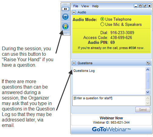
GoToWebinar has 2 ways to ask and respond to questions from Attendees. The Control Panel has a “Raise Your Hand” button that notifies the Presenter there is a question. Depending on time constraints, the Presenter may decide to un-mute and answer the question during the online session.  If there are more questions than can be answered during a session, the Organizer may ask that you type in questions in the “Questions Log” so that they may be addressed at a later time.

GoToWebinar_ControlPanel2

Pros and Cons 
I’ve put together what I consider to be the Pros and Cons of online training for CAD Software programs. Please pitch in and offer your comments.

Pros

  • Can eliminate travel time and expenses
  • Very cost effective option for customized one-on-one training
  • Allows for personalized, absolutely customized training because it’s normally one on one.
  • Can’t find a local trainer? No problem. Felicia Provencal can train you from Hawai’i – although you may want to go to her!
  • Can be set up within minutes if there is a pressing technical support issue or project that suddenly comes up.
  • Can be scheduled in shorter blocks of time – one of the best ways to make sure you retain what you are taught. I like to schedule 2 hours maximum per session.
  • Shorter blocks of time allow for easy customization of training topics from one session to the next. If more time is needed on certain features, it’s easy to squeeze in another 2 hour session.
  • It IS interactive!
  • All sessions can be recorded and played back at your convenience for a refresher.

Cons

  • Some people are more comfortable sitting beside and working directly with the trainer
  • It’s less interactive than hands-on, in person training.
  • For hands on training and depending on the material being covered, it may not work as well if you have several folks needing training at one time.
  • Requires a high-speed connection and a telephone headset allowing two hands on keyboard. A speakerphone can be used as long as feedback doesn’t become an issue.

Real World Example
I recently worked with a client from out of state. He is a grading contractor who thought he needed Carlson TakeOff training but, after some discussion, realized training in basic CAD (IntelliCAD) needed to come first and then TakeOff training.

The initial proposal was for me to travel there and spend 3-4 days training this client plus a second person (a competitor, in this case) who needed the same training. Both of them decided to give online training a try.

We scheduled online training for every morning one week. I worked with one from 7:30 – 9:30 am and then with the other from 10:30 – 12:30 pm. After the 3rd day, we had covered so much material that one asked to skip the next day so he could work with it himself and apply what he’d learned so far.

We ended up skipping two days. By the time we met again, he’d worked with it enough and become so much more proficient with the basic CAD operation that we were able to fast-forward through the next couple sessions and started working on his current project. Another subsequent session was cancelled because the rain finally stopped!

And then a few days later, he needed to get his project finished and out to bid. So, after our first session one morning, we set up another session at 4:00 that afternoon and worked until almost 7:00 that evening.

Both customers ended up very happy with the amount of material we covered and where they were with the software when we wrapped up our regular training. They still have the video recordings of the training for their reference to go back to when needed. In the end, the cost was almost the exact same as it would have been had I fulfilled the original proposal but they both learned and retained much more because the training was customized and personalized to their specific jobs.

Originally posted on Carlson Connection by Jennifer Dibona