New Carlson Build – 120219

Carlson released a new build of their desktop software earlier this week. This includes updates to the IntelliCAD/for AutoCAD versions of Survey, Civil, Hydrology, GIS, Basic Mining, Geology, Underground Mining, Surface Mining, Natural Regrade, Field, Takeoff, Construction and Point Clouds.

To confirm your current build number, go to Help > About Carlson. You’ll see the build number on the top line of the text box.

You can download the latest full version or updates to your current installation here.

If you would like to try out any of the Carlson Software products for 30-days, email me here.

For those anxious to try out the very latest and greatest updates in the testing versions of IntelliCAD 7.1, you can also send me an email to gain access to a new blog, “The Little CAD Engine That Could”, administered by Leonid Entov of Carlson Software.

Participation in the testing and access to the blog is by invitation only, so email me and I’ll pass along your request.


2011 End of Year Specials

As they do at the end of each year, Carlson has announced some “End of Year Pricing Specials” for their software. The best office software deal this year is for Carlson Civil Suite 2012 including one year maintenance.

I am discounting my prices further so I am prohibited from advertising my pricing for Civil Suite at all. Please call me at 919.417.8351 for a quote or email me for a coupon code that can be used in our online store.

Carlson is also discounting the Surveyor+ RTK GPS System. If you purchase through me by 4:00pm ET on December 31, 2011, my price on the system is $10,995 and includes full SurvCE Complete for Total Station, Robotics, GPS and Advanced Roading. If you have questions please call me at 919.417.8351 or Jeremy Taylor at 919.337.7998. We do have financing options available.

I also have one copy of Carlson Takeoff available at a significant discount – first come, first served! Again, you’ll have to call me to find out the price or email me for a coupon code that can be used in our online store.


Picks and Clicks: Conquer Problem Drawings

This article originally appeared in the February 2011  issue of Professional Surveyor magazine.

While working with IntelliCAD, AutoCAD, or any other AutoCAD-based programs, we’ve all 
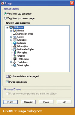
encountered the proverbial drawing from “you-know-where” that seems to drive us crazy from start to finish. Here I offer several tips to help you identify problems and conquer your problem drawings. I’ve listed these tips in the order I would apply them.

1 Purge your drawing.

The PURGE command removes any unused layers, linetypes, text styles, shapes (for linetypes and text), and many other items in the drawing.

When you run the purge command once, it will purge those items that are not currently in use and that have no other dependencies. For example, if a particular linetype definition depends on a particular shape, the purge command will delete the linetype definition only on the first pass.

Purging again will now delete the shape because the dependent linetype no longer resides in the drawing. Enabling the option to “Purge nested items” before purging will automatically execute the command repeatedly until all unused and dependent items are gone.

2 Purge remnants of registered applications that have accessed your drawing.

Typing “–PURGE” will execute the command line version of the purge command. This version includes a few options not available from the purge dialog box.

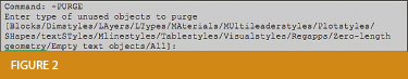
One of the extra options is “Regapps,” which is available only from the command line version of the command. You access it by typing “R” when prompted. This option removes “leftover” data from other programs (registered applications) that have been used to work on the drawing file.

3 Audit the drawing.

The AUDIT command looks for discrepancies between the objects displayed on the screen and the objects’ definitions in the drawing file database. The command then gives you the option of correcting the errors it has found. This command can be executed only while the drawing is open and active.

4 Recover the drawing and all reference files.

The RECOVER command is a more robust version of the audit command and can be used to open drawings that are so corrupt they cannot be opened otherwise.

Starting the recover command prompts you to browse to and select the problem drawing. If the problem drawing is already open and active, recover will prompt you to save changes before reopening the drawing and starting the recovery process.

For drawings that have attached XREFs (external references), use the RECOVERALL command to open and repair the selected drawing plus all dependent XREFs. Note that errors corrected by the audit are not saved back to the XREFs.

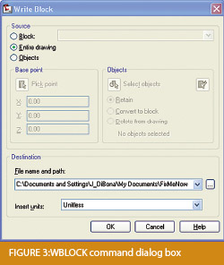
5 Block out the drawing contents to a new drawing.

If you suspect a drawing has become corrupt, you can WBLOCK the entire drawing out to another file. After starting the wblock command, set the “Source” option as “Entire Drawing” and provide the location and name for the newly created file.

Note that this command saves only Model Space entities to the new drawing. If needed, use AutoCAD Design Center to transfer layout tabs.

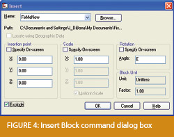
6 Insert the problem drawing as a block into a new drawing.

Using the same principle as above, you can use the INSERT command to bring the Model Space contents of a problem drawing into another drawing. Doing this will reduce or eliminate corruption in the problem drawing.

Make sure to use 0,0,0 as the insertion point and set the rotation angle and scale appropriately.

As with wblock, this command saves only Model Space entities to the new drawing. If needed, use AutoCAD Design Center to transfer Layout tabs.

7 Export drawings from vertical programs to AutoCAD.

Autodesk products such as Land Desktop or Civil 3D create program-specific, proprietary entities such as AEC Contours and AEC Point Objects. These proprietary objects can become corrupt or otherwise create problems when being accessed from standard AutoCAD or another program that doesn’t recognize the proprietary entities.

You can enter the -EXPORTTOAUTOCAD command at the command line to create a new drawing file that strips out the proprietary entities and leaves only standard AutoCAD entities. For instance, a Land Desktop or Civil 3D drawing containing AEC Contour entities will result in elevated polylines with text when exported to Autocad. And a Land Desktop or Civil 3D drawing containing AEC Point entities will result in a block with attributes when exported to AutoCAD.

Note that any AEC Objects will obviously lose their intelligence, but the new drawing can be opened in any version of Autocad.

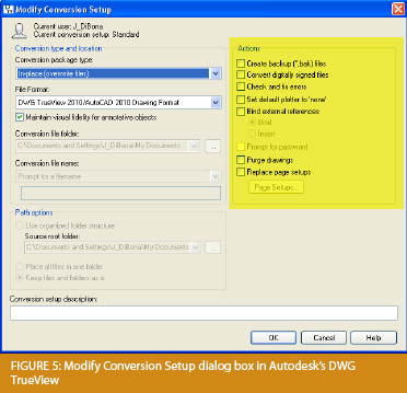
8 Use DWG TrueView Convert to fix errors and bind XREFs.

DWG TrueView is a free program that you can download from Autodesk’s website. It is most valuable for its ability to convert drawings to earlier versions individually or in bulk. In the Conversion Setup dialog box, you can specify one or more options to clean drawings during the conversion process.

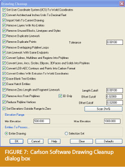
9 Use the Drawing Cleanup command in AutoCAD Map or Carlson Software.

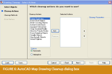
Both AutoCAD Map and Carlson Software provide Drawing Cleanup commands that provide a variety of cleanup tools. In either version, you have the option of performing one or more cleanup tasks on the entire drawing or on only selected entities in the drawing.

Note: Use these commands with caution and apply cleanup options incrementally to avoid making unwanted changes. Also, I recommend making a backup copy of the active drawing before performing this command.

If you use AutoCAD Map, Land Desktop, or Civil 3D, you can access the Drawing Cleanup command from Map ➜ Tools. In Carlson Software, access it from the File menu.

10

I’ve come up with 9 tips that will help you clean up and, maybe, access drawings that have become corrupt. To round out the list and make it an even 10, I’d like to hear from readers to find out what your favorite drawing recovery and cleanup tools are. Please email me at [email protected] and I’ll report in a future column.

This article originally appeared in the February 2011 issue of Professional Surveyor magazine.


Carlson Software Manuals

Looking for Carlson Software manuals? Prior to the 2010 release, Carlson included printed manuals with your purchase and, in addition, the manuals have always been available to print for yourself from the Help files.

With the 2010 release, Carlson “opened” a storefront on the self-publishing site called Lulu.com. You can order 2009 and 2010 Carlson Software manuals here http://stores.lulu.com/carlsonsw.

Originally posted on Carlson Connection by Jennifer Dibona


Carlson 2010 Is Here

The 2010 version of Carlson software running with IntelliCAD is officially available. This version offers support for 64-bit operating systems, Windows 7, and AutoCAD® 2010. This release is available from the Carlson website for download, or contact us for more information on requesting a demo CD. For those of you on the Carlson maintenance program, you may download the latest release from the Software download section of the Carlson website which can be found here.

If you are already using Carlson software and are part of their maintenance program, the Carlson update page has a new feature that allows you to receive your 2010 serial numbers through an on-line lookup feature. This can be found here. If you want to install your 2010 upgrade immediately, use this tool to look up your serial number, then download and install the software. CD’s will be shipped out to maintenance customers automatically, but you don’t have to wait, you can get started with all of the new features today!

To view the archived webinars covering several of the new features of this release, please visit the Carlson webinar archive here.

More information on this latest release will be provided as it becomes available.


Update by Jennifer: You can download a PDF with a list of Improvements in 2010 here:  Carlson 2010 Improvements

Originally posted on Carlson Connection by Felicia Provencal


Dewberry – Aligning Technology with Business Strategy

Some of you may have heard David Palumbo, PE, Technology Manager for Dewberry, at the Carlson User’s Conference back in April.  For those that missed his presentation, his story has been published in CE News this month.  Read about the process Dewberry used to evaluate new technology, its impact on their business methodology, and how they planned the roll-out and implementation.  Regardless of the size of your company or the software you use, there are some good tips and pointers in this article.

http://www.cenews.com/article.asp?id=3928

Originally posted on Carlson Connection by Felicia Provencal


North Rotation: Using Twist Screen

There have been many debates in various blog posts, discussion group posts, and articles regarding what is the best way to handle North rotation on maps.  With AutoCAD-based systems, there were essentially two choices: you could set a User Coordinate System (UCS) or rotate the screen using a tool such as 3D Dynamic View.  Carlson Civil and Survey offers these choices with a twist.

One of the main drawbacks to setting up a UCS is that it can throw off calculations being made by your mapping/design software.  For example, point databases and external TIN files often refer to the coordinates used in the field, or that existed when the data was generated (such as the TIN being built).  If you change the UCS, the coordinates may be wrong, and you may end up with incorrect results for things such as profile generation.

Because of this, many people choose to rotate the screen without rotating the coordinate system.  In AutoCAD, the simplest way to do this was by using 3D Dynamic View (DVIEW).  The main drawback to the DVIEW command is that while the screen would be rotated, common tasks such as adding text and symbols would be more difficult as they would have to compensate for the rotation of the screen.  This was usually managed using a setting called SNAPANG, which could be set to the opposite of the DVIEW rotation, making the use of ORTHO mode viable.  In AutoCAD-based systems, this would be fairly tedious, particularly if you wanted to match the rotation to a specific item, such as a portion of a road centerline.

In any of the Carlson desktop applications, there is a View pull-down menu with several commands that can solve this issue, often with a single click.  To see the most commonly used options, go to the View pull-down menu and choose the Twist Screen sub-menu.  There are four commands available, each one rotates the screen and automatically sets the SNAPANG to match.

  • Standard – This option allows you to select a rotation angle using the mouse.
  • Line, Polyline or Text – This option allow you to select an object to set as a view baseline.  It is the most useful when trying to match views to objects such as property lines or road centerlines.
  • Surveyor – This option prompts for the manual entry of a bearing or azimuth for the rotation angle.
  • Restore Due North – This option returns the screen to the orientation where North is straight up.

By using these options, you can quickly set up plot sheets and layout tabs, annotate the maps appropriately, and preserve the coordinate system for future design work or other calculations.

Originally posted on Carlson Connection by Felicia Provencal


Engineering, Construction, and BIM

There have been many articles, discussions, and presentations on Building Information Modeling in the recent months.  If you haven’t already heard the basics, this post covers it well.  For surveyors, civil engineers, and construction firms, there are two things you should know about BIM and how it will impact your business.

First, BIM is very similar in its goals and processes to GIS.  Basically, you are attaching data and other information to objects.  This allows you to manage the facilities after they have been built and track their contents over time. This is very similar to how as-builts of infrastructure are managed and tracked through a GIS system. Water and storm sewer sytems, telecomm transmission lines, and landscaping are types of things that are traditionally managed using GIS.  The information age has dramatically opened up opportunities for professionals to gather, collate, and attach data to their surveys, designs, and as-builts. 

Secondly, since buildings are not constructed in isolation, they must tie into the site grading and infrastructure, further opportunities for designers and contractors have opened up.  Complex site plans showing how the grading, structural design, and utilities will all connect are now possible, and represent a new deliverable for firms to offer their clients.  Carlson Software offers many solutions for creating these models and because Carlson data migrates well between various CAD and GIS platforms, owners and developers of these projects can be assured that their designs will be ready for management once construction is complete.

Originally posted on Carlson Connection by Felicia Provencal