BIM is not GIS

As someone quite entrenched in both disciplines (Civil and Architectural), I’ll add my 2 cents worth on the BIM vs. GIS subject.

In my opinion, BIM and GIS are both “methodologies” rather than “products”. The acronyms each have their own meaning and refer to designing, building, and managing information in a full life-cycle.

Each discipline has its own standards; from CAD standards to design standards (think of AIA vs. AASHTO), but both BIM and GIS rely on correct As-Built data to provide accurate information about their models.

BIM
The National BIM standard states the definition of BIM as:

BIM is best thought of as a digital representation of physical and functional characteristics of a facility…and a shared knowledge resource for information about a facility forming a reliable basis for decisions during its life-cycle; defined as existing from earliest conception to demolition.”

Autodesk has taken the BIM acronym that has provided a great deal of success with their Architectural Modelling packages and applied it to their Civil products as well. Their logic appears to be that its a “3D” product, therefore it is a “BIM” product. I believe that it is irresponsible to change terminology to simply advance product sales.

On the Autodesk Web Site, Autodesk lists a number of products as being “BIM” products:

  • Revit
  • Navisworks
  • Design Review
  • AutoCAD LT
  • + several more

With the acronym meaning Building Information Modelling (with building being a verb OR a noun), its interesting to see products such as AutoCAD LT and Design Review being shown on the list.

Revit
Revit is a Design Tool that allows the storage of certain pieces of information as well as the ability to add custom fields (heating capacity, cooling capacity, etc.) to the actual objects.

Navisworks
Navisworks integrates information from multiple data sources to provide a cohesive collection of information (graphics and data) to analyze things such as clash detection (HVAC duct work clashing with structural components, etc.).

AutoCAD LT
AutoCAD LT is Autodesk’s low-end design package. Apparently, any DWG file creation tool is now a BIM product as well.

Design Review
Design Review is a light-weight DWF viewer and markup tool. While it has been used as a backbone of products such as FMDesktop, its neither a Design tool, nor a Modelling tool.

FMDesktop
Absent from the list is FMDesktop. FMDesktop was one of Autodesk’s tools for managing the Building Information and Autodesk just dropped the product (Note: There are dozens of Facilities Managent Products available that provide similar capabilities such as FM:Systems, Archibus, Tririga, Manhattan, Cadapult, Famis, and more).

In the 2006 – 2007 time frame (when Autodesk acquired FMDesktop), Autodesk themselves showed customers Power Point slides regarding BIM. These slides showed where the “Design”, “Build”, and then “Operate and Manage” processes were performed. FMDesktop was Autodesk’s solution to tell the story of the building lifecycle and where the information was to be managed. These were broken down into 2 sections: The “Data Collection” piece and the FMDesktop piece.

Data Collection incorporated the Design (several disciplines such as Architects, MEP Systems Engineers, and Structural Engineers) as well as the majority of the Build process. The FMDesktop piece overlapped the Build process and then took over for the “Operate and Manage” process.

In my opinion, building that model of information AND managing that information is the true test of a “BIM” solution. There is no 1 product that is a “BIM” product. Its a series of technologies that are incorporated to provide the “information”.

Ultimately, a database component is required to work with the graphical representation of data (which certainly could be referred to as the “Building Model”).

GIS
GIS is BIM’s counterpart whereby Geographic (position on the planet) information is being stored and managed.

Most end users might think of GIS solutions as Google Maps or Google Earth where they can enter an address and out pops a graphic representation of that location or directions on how to get there. The graphic is just the tip of the iceberg. Without the data, the graphic would simply be a pretty picture.

Just as with BIM data, GIS data utilizes design tools to build the graphics and As-Built data and then tools to expand upon the As-Built information.

While there are a number of individual products on the market to assist in the creation, manipulation and distribution of GIS data, a complete GIS system involves more than 1 product or techonology.

A couple of the common Design Products are: Autodesk Civil 3D and Carlson Civil Suite

AutoCAD Civil 3D
Civil 3D is an object-oriented design tool for Civil Engineering applications. Because the tool is object oriented, the end product is not easily distributable. The data can be transferred to other links in the GIS solution chain by using technologies such as LandXML, but the graphical interaction is lost in this process (i.e. the objects are lost).

Carlson Civil Suite
Carlson’s Civil products work with DWG files in an AutoCAD or IntelliCAD DWG format. Because the data is stored as compatible DWG information with external data files, the data is easily transferred to other products in the GIS solution chain.

Managing the data developed in the design process is the next component of the GIS life-cycle. A number of products provide those solutions: ESRI ArcGIS, Vueworks, and Custom Mapguide Solutions.

ESRI ArcGIS
ESRI’s shp (shape) and adn (coverage) files are quite possibly the most prevalent GIS specific data files available and are often integrated in GIS solutions. ArcGIS allows GIS solutions to be deployed similar to FM solutions in the BIM world.

Vueworks
Vueworks is an organization that builds GIS and Work Management solutions using the ESRI base applications.

MapGuide
MapGuide is Autodesk’s development environment to build GIS applications. It is often used in concert with ESRI, Microstation and Autodesk data files.

GIS Standard
While there is not yet a concensus on a singular GIS standard, there are independent Spatial Data Standards employed by each digester of GIS data. You can view some of those here:

Both GIS and BIM perform very specific functions in accordance with their own disciplines. While the terminology is often mis-used, they refer to unique information systems; BIM in the structural facility world and GIS in the geographic world.

Originally posted on Carlson Connection by Jon Luby


BIM for Civil… Not

Several months have passed since I made my original post BIM This, BIM That… What is BIM?. In that time, I have asked a lot more questions, read a lot more on the internet and had a lot of discussions with Ladd and Felicia and also read the post by one of our commenters. I think I’ve developed a more concrete idea about BIM and how it applies, or doesn’t, to the civil/survey world and where the various software packages stand in regard to their “BIM-ability”.

Now, after all this additional information has percolated in my brain, I’m drawing two main conclusions:

1. It’s a fact that the term BIM as it’s always been used applies to actual BUILDINGS – the noun form of the word. But, more specifically, it  starts with construction drawings/design data but then incorporates the as-built data and, over time, continues to grow and collect data through the entire lifespan of the building.

Nothing in all this discussion of “BIM for Civil” gets beyond construction drawings and design data of a civil project. Autodesk is trying to stretch the definition of BIM to cover Civil 3D even though they never move beyond the design process with it either.

Remember, we do not talk about “BM” or Building Modeling. And, we don’t work with “GS” or Geographic Systems. The “I” is THE critical factor. And the “I”, or Information, piece of BIM is so valuable because it chronicles and helps manage the building through its lifespan.

To be able to legitimately call what we’re doing with our Civil programs “BIM”, we would need to have a mechanism to attach some sort of database or information to the objects in our drawings.

I know, I know… that’s why Civil 3D is so great – you can attach data to the objects. But, remember, we’re talking about attaching AS-BUILT data to these objects. Even though we could attach data using Carlson GIS or AutoCAD Map or ESRI, it’s simply not part of our current project scope to go back into our construction drawings and update them with as-built data so that:

  • maintenance schedules are attached to roadway template surfaces based on asphalt type,
  • model numbers are associated to pump stations or
  • inspection reports and flow rates are attached to fire hydrant blocks.

My conclusion here is that neither of these products – Carlson nor Civil 3D – meet the true definition of a BIM for civil. Until we start addressing the Information piece for the lifetime of a project, starting with the as-built data, using the term BIM is wrong.

In my opinion, if anyone has the lead on this in the civil arena, it’s ESRI.

2. Just because we don’t yet attach as-built data to our objects doesn’t mean that the data we do attach to our objects isn’t valuable. But, leading to my 2nd conclusion, why is it valuable? It’s only valuable if it can be shared. And this is where I believe Carlson has the undisputed edge. The image below shows the number of formats and other programs that Carlson is able to import data from and export data to.

carlson_importexport

Originally posted on Carlson Connection by Jennifer Dibona


The Power of LandXML

 The ability to import and export to LandXML has been around for quite awhile, but I still get a lot of curious looks when I mention it in my training classes. So, what is it? And why should you be using it?

Why Should We Be Using It?

We’ve all become accustomed to saving archive copies of our drawings for various purposes but saving the corresponding project data is often overlooked. Retrieving the drawing file may allow you to recover proposed contours and profile grid, but the underlying “surface” is lost unless the project was also archived.

Importing and exporting using XML files is the most convenient way to convert, transfer and archive data created in Carlson Software, Land Desktop, Civil 3D, Eagle Point, TerraModel and, I’m sure, other programs.

But, What Is LandXML?

LandXML refers to a file format (.xml) containing data created in a civil/survey program. My recommendation is that ALL civil and survey data should be archived – progress, submittal and final archive – using LandXML.

The way I like to explain it is that we use XML files in the same way we used to rely on DXF files. They’re mostly outdated now, but DXF files are a generic file format that, for example, we used to convert MicroStation DGN files to AutoCAD DWG files. At that time, AutoCAD couldn’t read DGN files and Microstation couldn’t read DWG files; but both could read DXF files. So, we had to convert our drawing files to the generic DXF format that could then be read into the other program.

Similarly, Carlson Software, Land Desktop, Civil 3D and the other programs create their own unique files for civil/survey project data such as points, point groups, surfaces, centerlines, profiles, etc. When we have to pass that data onto someone using a different civil/survey program – it’s a nightmare!

That’s where LandXML files prove their value.

Exporting your civil/survey data to an XML file breaks it all down into, basically, a text file. Specifically, it’s an HTML file that can be viewed through a web browser such as Internet Explorer or Firefox. For instance, when a surface model (TIN) is exported to XML, the X, Y, Z values of each point on the TIN is assigned a number, and then each “face” (triangle) of the TIN is defined by specifying the 3 corners. See the examples below:

xmlpost_01 

xmlpost_02

Note that one type of data that is currently not supported in XML files is typical cross-sections or template files.

Another benefit of using LandXML to transfer or archive project data is that any combination or all of your project data can be saved in a single XML file. This is valuable because exporting ALL of the data for a project can create a massive XML file.

Even if you archive your project data in its native format, you should consider additional archiving in XML format. No one knows what kind data files we’ll be using 10 or 20 years down the road so saving your data in such a generic, text-based format such as XML files allows for easier retrieval down the road.

Originally posted on Carlson Connection by Jennifer Dibona


Working with Land Desktop or Civil 3D Contours in IntelliCAD-based Carlson Programs


If you are working in an IntelliCAD version of  Carlson Survey or Civil and need to bring in surface entities (contours) from a Civil 3D (C3D) or Land Desktop (LDT) drawing, it’s actually very easy to do. However, it’s not necessarily easy to find on your own. And, unfortunately, it’s in a slightly different place depending on whether you’re using the Carlson Survey or Civil menu.

FYI – If you simply try to “Open” a drawing that has AECC Contour Objects with an IntelliCAD-based program, it may look correct, but the entities will only be the dreaded “ACAD PROXY OBJECTS” that have bogus elevations. These are only good to look at… not work with.

Whether you’re using Survey or Civil, the only thing you’ll need is a drawing file (DWG) containing the C3D or LDT contours for the surface. It doesn’t even need to be opened, you just need to have it and be able to find it. (hey, I’m getting old!).

First, start a new drawing in Carlson.

Then, if you’re using Carlson Civil:

  1. Go to the “Surface” menu,
  2. Select  “Import/Export Surface”
  3. Then, select “Convert LDT/Civil 3D Surface Drawing”.

If you’re using Carlson Survey:

  1. Go to the “Surface” menu,
  2. Select “Import/Export Surface Data”
  3. Then, select “Convert Civil 3D Surface Drawing”.

Next, you’re prompted to “Select the LDT/Civil 3D Drawing to Read”. After browsing to and selecting the LDT or C3D file, pick “Open”.

Next, you’re prompted to to “Select Converted Drawing to Write”. This will be a new DWG file containing the converted data. After browsing to a new location and specifying a new file name, pick the “Save” button.

You’ll see the conversion process in the text window. Once finished, you can open the converted drawing.

What you will find in the new drawing are all of the entities from the original LDT/C3D drawing except that any AECC Contour Objects have been converted to elevated PLINEs and LINEs.

The first step you’ll probably want to take after opening the new drawing is to join together all of the contour PLINEs and LINEs. You may want to “Isolate” the layers for the contours first.

Then use the “Join Nearest” command under the “Edit” menu. Like most cases, make sure to have the “Join Only Common Elevations” and “Join Only Common Layers” options selected.

Originally posted on Carlson Connection by Jennifer Dibona


How Does Carlson Support Their Users? Ask David Farina

I’m going to post a LONG email stream between one of my clients, David Farina, Bruce Carlson and Dave Carlson. You can see the new feature that David requested and Bruce and Dave’s responses. David received a “development” version of the new features approximately a week after submitting this request.

I asked him for a statement describing his experience with Carlson:

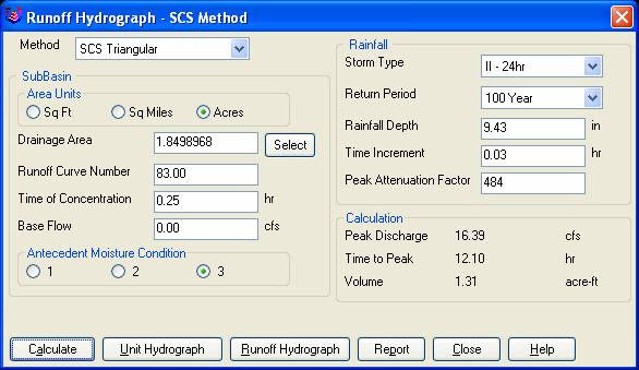
Recently I found that the Time of Concentration input boxes were inadequate under the hydrology portion of Carlson Civil Suite so I emailed a description of the problem to them. I was very impressed to get a phone call the same day. They discussed the problem with me and had a revised program update to me in under a week. I’ve been emailing Autodesk for over a year on problems with Civil 3D and never heard a peep. Needless to say I’m very happy with the customer service I have received from Carlson thus far.

Here is the original question from David Farina on March 4, 2009:

Jennifer,

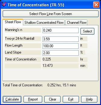
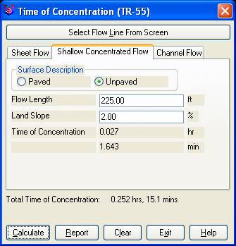
I was going through a mock project to learn the hydrology part of Carlson and noticed a critical deficiency in Time of Concentration input. The review agencies around here want to see the TR-55 method. First, the TR 55 minimum sheet flow needs to be 100’ instead of 300’. They recently changed it per the TR-55 Web site. Second, I don’t think I’ve ever had a project where you didn’t have to split one of these flow types into 2 or more mannings roughness areas.

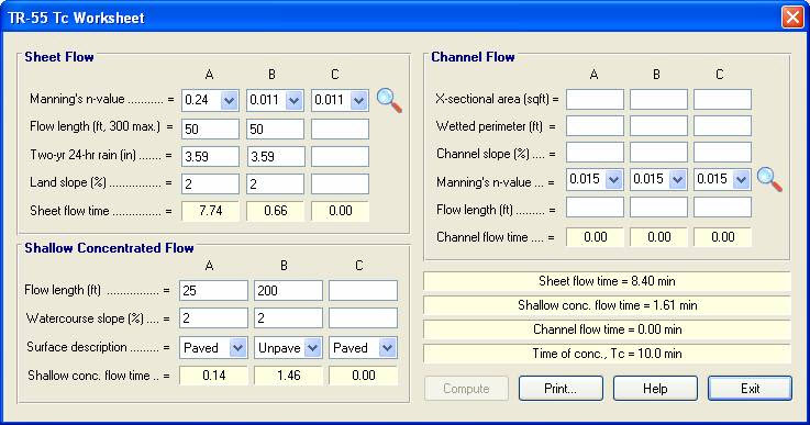
For example:  a flow path that starts on dense grass for 50’ then passes over asphalt for 75’ and back to grass for 200’ would need to be calculated as follows:

 Sheet flow 50’ Grass ->  Sheet flow 50’ Asphalt -> Shallow Concentrated flow 25’ Paved -> Shallow Concentrated flow 200’ UnPaved.

But as you can see the Carlson input only allows for one entry per flow type.

 df_01

 df_02


Below is the Intellisolve version:  Notice the A, B C

 df_031


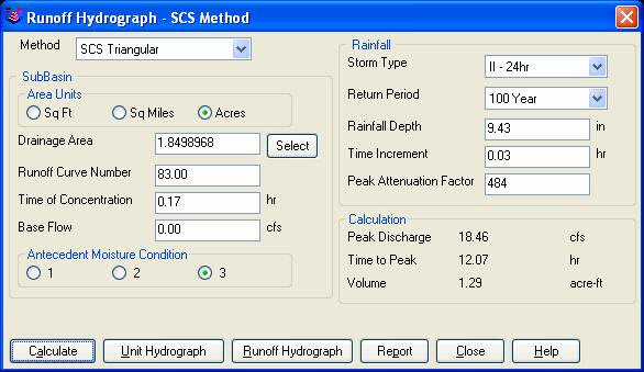
There is a 5.1 minute difference in TC results which results in a 2 CFS difference in the 100yr example below: 

df_04

df_05


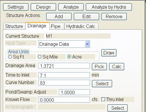
If the above example is that different then I am also concerned about how the Time to inlet is calculated in the example below:

 df_06


df_07

Was the SCS method used to get the 7.1 min value? 

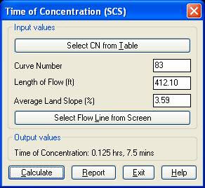
Notice the 7.5 value in the TC dialog to the right. 

This was the value if I SELECT FLOW LINE FROM SCREEN and pick the path that the dialog on the left generates.

Can I generate a report of how the time to inlet was calculated? 

Maybe there can be a button next to the Time to inlet to select TR-55

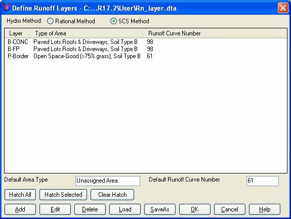
Maybe Mannings coefficients can also be put into the WATERSHED->DEFINE RUNOFF LAYERS to be used for this calc as the flow path passes through each polyline area the same way Carlson already calculates the composite CN.
df_08 

 Will any of this matter if we get HydroCAD and link it to Carlson?  

Just food for thought.


Thank You,

 David Farina

Senior Designer

I forwarded David’s question onto Bruce Carlson, President of Carlson Software, and Dave Carlson, Director of Programming, and received this response from Bruce:

Folks:  Excellent input—this will find its way into the next release for sure.  We’ve spent a lot of time studying Haested and matching numbers there on pipe flows in culverts, for example, covering all conditions—but do need to put to bed Time of Concentration for approved defaults and sub-catchment conditions as they vary within a watershed area.  This Intellisolve example is really helpful.  Also, I took in input at Jennifer’s Statesville, NC presentation Dec. 2007 that mentioned the new 100’ default and also mentioned:

Using Q=CIA, there are new “rules” being published that using larger pipes or it may be larger drainage areas, there is an added multiplier in the form Q=CIA*Q1 where Q1 is a table of values.  I didn’t get the full details, but we need to research this.

And in storm sewer design, if we are compositing the calc of time to inlet using a “short-form” SCS-style method, based on percentage area of various land uses and associated runoff coefficients, we need to have a Report button that documents the results for full vetting and reporting out by users, and we need to incorporate an additional auto-calculated, long-form TR55 time of concentration there as well that uses sheet flow, channel flow and shallow concentrated flow.  One key in all this is to be able to auto-distinguish these flow types from the DTM and land uses and have the forms filled out with default values, which the user can change.  

 Question I’m curious about.  Say you built a gentle 6’wide, 1% slope swale with 6:1 side slopes, hardly noticeable, mowable, between lots in a subdivision.  Would the flow in that be treated as shallow concentrated flow or channel flow?  When would one condition end and another begin, by definition, so we can get real precise on auto-calculating these using layers/land use types and DTM values?

 Good stuff, and it will get done.

Bruce Carlson, PE

Pres., Carlson Software

David added the following:

I think when to use channel flow should be determined by the width of the bottom of the channel and hence how deep the channel gets on an 2yr storm 24 storm.

You could have a channel with 1:1 side slopes but if the bottom was 50’ wide and the flow path started in the channel then

the first 100’ would still be sheet flow in my book. Unless of course a huge amount of water was entering the channel from another basin.

I think the concentrated and channel flow times (being in the fraction of a minute range) are so small and have such a small impact on overall time

compared to sheet flow (fraction of an hour) that you could pick an arbitrary number like 5’ wide bottom and smaller is channel flow and not upset the model.

Sheet flow probably makes up 80 to 90 % of overall TC if it is over grass.

Anyone disagree?

Thank You

Dave Carlson sent this on March 11, 2009


Hi David,

Here’s an update to the Tc by TR-55 routine that allows unlimited number of breakouts. This update is for Carlson 2009 on Acad 2007-09. To install, unzip and copy the arx to the Carlson2009LSP folder. Let me know if you need a different version or have more suggestions.

For the Storm Sewer Network routine, I put it on the to-do list to add a Select button next to the Tc to show the components that make up the Tc like the Select button does for CN. Also we will looks at adding Manning’s n to the Define Runoff Layers for use with Tc calcs.

Thanks for the input.

Dave

Originally posted on Carlson Connection by Jennifer Dibona


AutoCAD 2010 Release, Autodesk 2006 Software Retirement

Autodesk has announced that their 2010 products will be released on March 24, 2009. I found this post by Randy McSwain to be a good overview of the new features in AutoCAD 2010.

As of March 13, 2009, Autodesk no longer supports or offers upgrades from their 2006 products.

Because of the retirement of Land Desktop, I see that Autodesk is offering to crossgrade existing Land Desktop customers to Map or Civil 3D with special pricing. Subscription will probably be mandatory, but I’m not certain.

Originally posted on Carlson Connection by Jennifer Dibona


BIM this, BIM that… What is BIM?

 Q:     What is BIM? And, exactly how does it relate to the civil engineering industry?

 A:     BIM, by definition, has nothing to do with civil engineering.

BIM stands for “Building Information Modeling”. The term “BIM” originated in the Architectural world and, generally, defines the process of inputting information to and extracting information from a 3D model of a building/facility.

Definition of BIM from the National BIM Standard:

BIM is best thought of as “a digital representation of physical and functional characteristics of a facility…and a shared knowledge resource for information about a facility forming a reliable basis for decisions during its life-cycle; defined as existing from earliest conception to demolition.”

From the National Institute of Building Sciences:

Building Information Modeling (BIM) refers to the use of the concepts and practices of open and interoperable information exchanges, emerging technologies, new business structures and influencing the re-engineering of processes in ways that dramatically reduce multiple forms of waste in the building industry. The National BIM Standard, a key element of the overall industry transformation being supported and coordinated by the buildingSMART alliance™, establishes standard definitions for building information exchanges to support critical business decisions. Implemented in software, the consensus-based standard will form a basis for more accurate and efficient commerce within the capital facilities industry. The National BIM Standard is also intended to help participants in facilities-related processes achieve more reliable outcomes from commercial agreements.

From Geomatics International:

A Building Information Model (BIM) is a digital representation of physical and functional characteristics of a building. Construction and management of buildings involves many stakeholders, so that proper sharing of information over the entire lifecycle of a building is very important. The Open Geospatial Consortium (OGC) is developing BIM standards that promote efficient web-based information sharing in the Architectural, Engineering, Construction and building Ownership and Operation (AECOO) markets.

Because Wikipedia is open-source and able to be edited by anyone and everyone, the entry for BIM changes regularly. The entire entry looked like this as of February 26, 2009. Here is an excerpt:

Building Information Modeling (BIM) is the process of generating and managing building data during its life cycle[1]. Typically it uses three-dimensional, real-time, dynamic building modeling software to increase productivity in building design and construction.[2] The process produces the Building Information Model (also abbreviated BIM), which encompasses building geometry, spatial relationships, geographic information, and quantities and properties of building components.

A lot of confusion is now occurring because Autodesk and their civil resellers are trying to make the connection between BIM and Civil or, more specifically, Civil 3D. See examples here:

BIM for Civil Engineers by Sanjay Asnani, Autodesk
  If link doesn’t work, find this document HERE.

What Does BIM Mean for Civil Engineers? by Adam Strafaci, Autodesk

Civil 3D and BIM… How do they relate? by Melanie Santer, US CAD

However, if you simply Google “bim building information modeling” and look at the first two pages of returns, the only entries that attempt to connect BIM and civil engineering belong to Autodesk or one of their civil resellers. All other hits refer to BIM in an architectural/building sense. If there is a specific software program mentioned, it is Autodesk’s Revit product. A caveat to this is the civil/structural engineering specialty field of bridge construction which can also be modeled using Revit. Bridge construction is a bit of a hybrid in that it is similar to building design and can also legitimately be related to BIM.

Among Autodesk’s architectural team and resellers, most, if not all, references to BIM are solely in an architectural/building capacity. See examples here (pages were cached on 2/26/09):

Brave New BIM

The World According to BIM – Part 1

Summit AEC – Autodesk BIM & CAD Software

As you can see from the above links, it is technically incorrect to connect BIM and Civil. However, many in the civil world are witnessing the Autodesk definition of BIM take hold. So, in the event you are ever asked or required to “BIM” a civil project, you are essentially being asked to design and deliver a dynamic, 3d model of the entire project.

It is important to realize that creating a dynamic 3d model for a Civil project (or “BIM”ing a civil project) is not limited to using a particular software program.

Find a civil engineering design software that allows you to design to specific criteria, is able to show a great visual representation of all the components of your project in 3D view and is able to dynamically reflect changes and you can “BIM” along with the rest of the world.

Designing a project using a dynamic model allows you to design according to specific criteria such as AASHTO (American Association of State Highway and Transportation Officials) standards or by specifying minimum/maximum values for storm or sanitary sewer design. It also is invaluable to detect, before construction, potential conflicts between a proposed network of roads and associated utility networks. As an example, a dynamic 3d model would trigger a warning if, when lowering a roadway, the rule for minimum cover over a pipe on an adjacent roadway has been violated. Also, creating this model allows you to view the model, make changes to vertical alignments and see dynamically updated cut/fill quantities all at once.

To reduce the confusion, it might be time to coin a new term such as “Site Information Modeling” to describe the process in the Civil industry. But, there is still quite a disparity between the “Information Modeling” done for a Building compared to that done for a Civil project. In true BIM, the “I” (Information) component is as important as the “M” (Modeling) component because determining usability and functionality of the Building through its lifecycle is one of the goals of BIM. At this time, the process on the Civil side is still much more about the “Model” and not nearly so much about the “Information” going into and coming out of the model. When we are able to incorporate results of traffic flow analyses for a roadway or inspection reports showing sludge build-up and flow capacities in sewer/storm pipies and manholes, we will be truly using the “Information” as it was intended in an “Information Model”.

Originally posted on Carlson Connection by Jennifer Dibona


Top Myths About Carlson Software

I’m asked many of these questions on a fairly regular basis and thought it was time to look into some of them and provide the fullest answer I could. Where possible, I’ve researched and found the answer myself. In a few cases I had to rely on Carlson representatives to supply the answers.
  
Myth #1  Autodesk stopped working with Carlson in February 2008. 
  
 False. In February 2008 Carlson simply stopped being a reseller of Autodesk products.

In other words, if you want to run Carlson on top of AutoCAD, Map, Land Desktop or Civil 3D, you’ll have to buy it from an Autodesk reseller instead of from Carlson. Carlson remains part of Autodesk’s Developer Network (ADN) and is listed on Autodesk’s partner page. The ADN designation provides tools to developers to help build their products on top of Autodesk products. As a point of comparison, Eagle Point Software is also a development partner of Autodesk.
  
 
Myth #2  Carlson is owned by Autodesk or, (“bonus”-myth) Carlson will be sold to another, larger software company. 
  
 False. Carlson Software was started in 1983 by Bruce Carlson and remains a private, family-owned business. No one can absolutely guarantee the future, but I have heard Bruce Carlson speak many times about the value he places on competition in the marketplace and his belief that the consolidation of many other software companies has come at the expense of the end-user of the software.

Selling out? I don’t see it. But partnering? Yes. Carlson places a great deal of value on working with any company who wants to work with them.   Click on the image below to see the many different programs Carlson imports data from and exports data to.

Carlson Import and Export Options

Myth #3  Because Carlson Software uses basic AutoCAD entities instead of “intelligent objects”, it does not have 3D or dynamic abilities. 
  
 False. Carlson Software uses basic AutoCAD entities so that all drawings produced by their programs can be easily shared with any other DWG- or DXF-compatible program, regardless of version. Carlson has figured out a way to have the dynamic reactions work on basic entities such as lines, polylines and text. One example would be having profiles and storm drain structures automatically adjust their elevation as a centerline alignment is edited and changed along a surface. And, all of this happens without having to fight the dreaded “proxy objects”!  
 
Myth #4  Because Carlson now works on top of Intellicad, it no longer works on top of AutoCAD-based products. 
  
 False. Carlson Software has always worked on top of AutoCAD-based products and, if you listen to Bruce Carlson discuss the issue, hopes to always continue doing so.

In April 2008, Carlson began giving their customers an IntelliCAD-based “stand-alone” copy of their software with every purchase of Carlson Civil, Survey, Hydrology, GIS, TakeOff and other programs. (IntelliCAD is widely described as an “AutoCAD-clone”. You can read more HERE.). This, again, gives more power and options to Carlson users because it allows the user to choose whether to run Carlson on top of practically any version of AutoCAD, AutoCAD Map, Land Desktop, Civil 3D or on top of IntelliCAD.

Also, with their Sight Survey program (launched in 2008), Carlson created their first program to run on top of MicroStation.

At last year’s 25th Anniversary users’ conference, Bruce Carlson stated that Carlson hopes to have their software working on 4 different platforms within the next few years: IntelliCAD, AutoCAD, Microstation and ESRI. 
  
 
Myth #5  Carlson doesn’t have CIVIL “BIM”-ability. 
  
 First, the premise of the statement is incorrect. BIM (Building Information Modeling), by definition, has no relationship to the civil engineering industry. It is architectural in scope and refers to actual buildings and facilities.

However, for several reasons there has been a push to re-define the term BIM to apply to Civil Engineering (in general) and Civil 3D (in particular). When discussing BIM in the context of Civil Engineering, it simply means that a software program has the ability to:

  • design to specific criteria
  • show a great visual representation of all the components of your project in 3D view and
  • dynamically reflect changes to your project.

Can Carlson Software do all that? Absolutely.

Carlson can, and has been able to, produce true 3D models of civil/survey/utility project sites for years. These models can be viewed in 3D and quantities are dynamically updated whenever the model changes.

Because Carlson has strongly served the U.S. mining industry for over 20 years, they long ago developed features for grading, material quantity calculations and surface viewing and visualization to meet the demands of this industry. In fact, the civil industry pales in comparison to the mining industry in regard to these demands.  
 
Myth #6  Carlson has only been developing civil software since 2007. 
  
 False. To make sure I got this right, I asked the folks at Carlson for help and received the following in response:

Bruce Carlson began developing his software for the mining industry in 1983. By 1984, the program was able to extract profiles and cross-sections, calculate volumes and design road profiles. 3D Surface viewing abilities have been available in Carlson Software since the early 1990’s.

Carlson developed the stand-alone Carlson Survey program in 1996 and in 1999 Autodesk contracted to market and sell a version of it called “Autodesk Field Survey”. Autodesk did away with Field Survey after a few years and Carlson migrated most users over to Carlson Survey where it has grown to become a favorite of surveyors.

Various civil features were organized as modules in a package called SurvCADD that was released in 1989. The civil engineering routines were renamed as Carlson Civil in 2006.

The first Hydrology module for Carlson was released in 1993. It was re-packaged as Carlson Hydrology in 2006.

Carlson Hydrology was the first and, I believe, is still the only H & H software to function entirely within the DWG-environment. If I learn differently after this document is made public, I will post a correction in this space.
  
 
Myth #7  Carlson may have found a spot in some surveying firms, but larger firms aren’t using it. 
  
 False.  Again, I requested generic customer data from Carlson and was told that,

Among our 30,000+ users, there are many DOT agencies and also ENR Top 50 firms using Carlson Software. Carlson Software is very experienced in working with large firms, due to their mining background. All 20 of the top 20 U.S. coal companies use Carlson Software at some level, most being standardized on the software for mine planning and design.

As far as my personal experience, I’ve only been working with Carlson Software for a couple of years and companies I work with tend to have fewer than 25 users. I can personally say that I have seen or know of a few large firms who have moved to or are in the process of moving to Carlson.

These do not include the many customers of mine who have recently let their software contracts lapse, purchased one or more seats of Carlson and have told me they plan to purchase and implement Carlson when the economy rebounds. 
  
 
Myth #8  Carlson Software does not support the full project lifecycle – Concept to Completion. 
  
 False. I think Carlson probably has the project lifecycle covered better than any other software firm in existence.

Carlson Software has data collection, survey processing, civil design, hydrology, GIS, construction material takeoff and machine control software in their stable. 
  
 
Myth #9  Carlson Software doesn’t have the support system in place to adequately support its users. 
  
 False. Carlson provides free technical support directly out of their Maysville, KY and Boston, MA offices. Again, I have heard Bruce Carlson say that keeping tech support free and in-house ensures that their software will remain easy-to-use and that the company will always be responsive to the wishes of their customers.

If a bug or other problem with the software is encountered and logged into Carlson’s tech support department, the corrected files will be emailed to you as soon as the programmers develop the fix. Periodically a collection of the updated files will be released to all users as a maintenance patch. These updates are available to all users whether or not they are under a maintenance contract with Carlson.

I received this testimonial from a customer on March 13, 2009.

“Recently I found that the Time of Concentration input boxes were inadequate under the hydrology portion of Carlson Civil Suite so I emailed a description of the problem to them. I was very impressed to get a phone call the same day. They discussed the problem with me and had a revised program update to me in under a week. I’ve been emailing Autodesk for over a year on problems with Civil 3D and never heard a peep. Needless to say I’m very happy with the customer service I have received from Carlson thus far.”

David Farina, CCAD Engineering
– Greenville, SC

Other examples of Carlson’s responsiveness:

Example 1: The ability of the Carlson Civil & Hydrology “Design Bench Pond” command to have multiple interior benches was added to the software after an attendee at a workshop I held in Raleigh, NC in December 2007 requested it.

Example 2: In the LotNet command, the prompts asking users to specify minimum and maximum building offset distances for lot layout generated too many tech support calls. In the next release, the prompts were re-worded to make the intent more clear.

Example 3: The LotNet command now allows you to designate “sub-areas” (such as wetlands, stream buffers, poor soils, etc.) to be excluded from your area to be subdivided during the lot layout routine. This request came from a prospect during a demonstration in Raleigh.

Example 4: I understand that Carlson’s tech support team was bombarded by requests to change the default cul-de-sac location from the “Start” of the road to the “End” of the road in the RoadNet command. This was changed in the 2009 release.

Example 5: The ability to draw multiple building pads inside lots during the lot layout routine in LotNet was requested by a firm out of Savannah, GA. 
  
 
Myth #10  Carlson Software can’t share data with Land Desktop or Civil 3D. 
  
 False. Carlson has many tools in their software to import civil/survey data from and export data to Land Desktop and Civil 3D. It can be said that Carlson Software works with Civil 3D data as well as Land Desktop or any other civil/survey software and also works with Land Desktop data as well as Civil 3D or any other software.

Carlson has LandXML import and export functionality, can directly convert Land Desktop points and contours into Carlson points and contours and also imports a Civil 3D surface as elevated contours.

Regardless of the civil/survey software being used, LandXML is the best mechanism to import/export a surface model because it maintains the TIN lines of the surface. 
  
 
Myth #11  To be continued. 
  
 If anyone thinks of other question(s) they’d like to supply, please email me HERE. I’m open to suggestions and don’t mind expanding beyond 10 Myths.

Originally posted on Carlson Connection by Jennifer Dibona