Did you know… About the Flatten Command?

FLATTEN is an Express Tools command in AutoCAD and a standard command in IntelliCAD. It allows you to quickly convert 3d objects to a 0-elevation, flat version of itself.

Most of us in the civil/survey world have gotten frustrated when we’ve received a drawing from someone who used lines more than polylines and apparently snapped to everything in the drawing that had an elevation! The result is that you have lines drawn on a slope and with which it’s nearly impossible to inverse distances or even perform simple drafting commands.

So, next time that happens, try the FLATTEN command and see if that helps get things back where they’re supposed to be!


Did you know… about all the different selection methods in CAD?

Anyone who has used AutoCAD or IntelliCAD for any period of time will be familiar with a few of the selection methods available to you during editing commands… although you may not know the “official” name of the method.

When your Command: line prompted reads “Select Entities:”, you can use the following methods to add entities to the selection set:

A Single selection is when you use a “Pickbox” to select one entity at a time.

An Implied Window selection is when you drag a rectangular area, from left to right, around the entities to be selected. This method will select any entities that are fully enclosed within the area. To force a Window selection, you can also type “W” at the Command: line when prompted to “Select Entities:”. Window selections are indicated by the solid outline of the rectangle and a color shading within the rectangular area.

An Implied Crossing selection is when you drag a rectangular area, from right to left, around or across the entities to be selected. This method will select any entities that are fully enclosed or touch (cross…) the outline of the rectangle. To force a Crossing selection, you can also type “C” at the Command: line when prompted to “Select Entities:”. Crossing selections are indicated by the dotted or dashed outline of the rectangle and a color shading within the rectangular area.

So, these are the ones you probably know about. But, what about these?

Again, when prompted to “Select Entities:”, you can do any of the following:

Hold the SHIFT-key down while selecting objects using Single, Implied Window or Implied Crossing selection methods will un-select any objects previously selected.

Type “P” at the Command: line to use the Previous selection method. This method will automatically select the same objects that had been selected for the most recent editing command. This obviously doesn’t work if the Previous selection set has been ERASEd from the drawing.

Type “L” at the Command: line to use the Last selection method. This method will automatically select the entity most recently added to the drawing. The entity must also be visible on the drawing screen in order to be selected.

Type “ALL” at the Command: line to use the All selection method. This method will automatically select all entities visible in the current space.

Type “F” at the Command: line to use the Fence selection method. This method allows you to drag a line (by picking points) across the entities to be selected. When picking the points for the Fence, the sketched line is dashed or dotted. This method is similar to a Crossing selection as it will select anything that touches the Fence.

Type “WP” at the Command: line to use the Window Polygon selection method. This method allows you to sketch an irregularly shaped area (by picking points) around the entities you wish to select.  Any entities that are completely inside of the non-rectangular area will be selected. This is simply a non-rectangular version of the Window selection method. Window Polygon selection areas are indicated by the solid outline  and color shading of the irregularly shaped area.

Type “CP” at the Command: line to use the Crossing Polygon selection method. This method allows you to sketch an irregularly shaped area (by picking points) around or across the entities you wish to select. Any entities that are completely inside of the non-rectangular area or touching its outline will be selected. This is simply a non-rectangular version of the Crossing selection method. Crossing Polygon selection areas are indicated by the dashed or dotted outline  and color shading of the irregularly shaped area.

If you have a complex selection set and need to un-select several entities, you may find it impractical (and frustrating) trying to un-select everything by using SHIFT+<select> to do so.

Another way to un-select a bunch of entities is to use the Remove selection mode. When prompted to “Select Entities:” at your Command: line, type “R” to change your Command: line prompt to “Remove Entities:”. Now, any entities you select, using any method, will be Removed from the selection set. You do not have to hold SHIFT and you can use Fence, Last, Window Polygon, etc. to remove those items.

After Removing entities from the selection set, type “A” at the Command: line to return to the Add selection mode. This changes the Command: line prompt back to “Select Entities:” and you will once again be able to Add objects to the selection set.


Did you know… About the Change Space Command?

Some of us are old enough to remember life without the CHSPACE command… and what a great addition it was when the command was finally introduced to AutoCAD several years ago. And, with the release of IntelliCAD 7, it’s now in that program as well.

CHSPACE is a command that allows you to move one or more entities from Model Space to Paper Space (or vice versa) very easily. In AutoCAD, the operative word there is “MOVE”. You have to be a little careful because the command does exactly that: It MOVES it from paper to model or from model to paper. In IntelliCAD, you are given the option of COPYing the selected entities from one space to the other.

The command actually does more than just move or copy selected entities, it also scales the entities by the viewport scale so they’re correct size-wise. For instance, let’s say that you have a drawing in model space that’s been rotated so that it more easily fits on a sheet of paper. Also in model space, you’ve inserted a North arrow. And, in paper space/layout view, you have inserted a title block at a scale of 1:1 (18″ x 24″, etc.). Inside of the title block, you’ve created a viewport you’ve scaled to 1″=40′.

For drafting purposes, it’s desirable to have the North arrow in paper space to that it can be moved around and positioned outside the viewport. If you’re in AutoCAD, the first step is to make a copy of the North arrow. If you’re using IntelliCAD, this step isn’t necessary. Then, while in paper space/layout view, double-click inside the viewport to make it active. Type CHSPACE at the Command: line. Follow the various prompts within the command and Voila! Your North arrow is now in paper space and it’s been scaled down by 40 times so that it fits properly on your title block.


Carlson 2013 Has Been Released

Carlson released the 2013 version of their desktop products today. This includes: Civil Suite, Civil, Survey, Hydrology, GIS, Takeoff, Construction, Point Cloud, Geology, Surface/Underground Mining and Natural Regrade.

The 2013 embedded-AutoCAD versions of Takeoff and Survey have not yet been released.

Unlike previous versions of Carlson that support running on top of IntelliCAD or AutoCAD products 2000-2012, Carlson 2013 can only be run on IntelliCAD or AutoCAD products 2004-2013. This includes AutoCAD, Map, Land Desktop and Civil 3d. Also, anyone using the FREE IntelliCAD that comes with Carlson is eligible for a FREE GIS Starter Kit from Esri which includes ArcMap.

You can download Carlson 2013 here.

If you are using 2012 and are current on your annual maintenance contract, you can click here to look up your new 2013 serial number online. You will need to enter your contact information and your 2012 serial number in order to generate the 2013 serial number. You can find your serial number by opening Carlson Software and going to Help > About Carlson Software > Change Registration.

If you have trouble finding your serial number or would like to know the cost to upgrade to 2013, please email me with your request.

Click here for the full list of improvements to Carlson 2013

Click here for improvements to the General commands in 2013

Click here for the additional data file & conversion support in Carlson 2013

Click here for improvements to Survey commands in 2013

Click here for improvements to Civil commands in 2013

Click here for improvements to Hydrology commands in 2013

Click here for improvements to GIS commands in 2013

Click here for improvements to Takeoff commands in 2013

Click here for improvements to Point Cloud commands in 2013

Click here for improvements to Geology commands in 2013

Click here for improvements to Surface/Underground Mining commands in 2013

Click here for improvements to Natural Regrade commands in 2013


Did you know… that you can print your CTB files?

Several years ago when I started my business, my first contract was as an outside CAD manager for a civil & land planning firm. In trying to document their pen weights, screening, etc. I found a utility available on Autodesk’s website that allowed me to export all the values in a CTB file to a .csv file that could be opened (and printed) with Excel.

Here is the old Autodesk Knowledge Base article – it still works for anyone using AutoCAD-based programs version 2007-2008.

Unfortunately, I haven’t been able to find a more current version of this utility until recently. Govert’s Tools has a program called PlotStyleViewer. You can download it here.

In his words,

This inspired me to create a CTB/STB view/print application that works completely independent of AutoCAD and Autodesk tools! The program consists of just one executable file, there are no other exe’s or dll’s needed. It should work with CTB’s/STB’s from AutoCAD 2000 upto the latest version. The purpose of this tool is that you can view CTB’s, print them and save as text file that you can open in Excel etc.

It’s a handy little utility and doesn’t seem to be limited to a particular version. Hope you get as much use out of it as I do.


Software Review: AutoCAD and IntelliCAD

The May 2012 issue of Professional Surveyor magazine has been published. This month they are featuring a software review I submitted: AutoCAD and IntelliCAD.

You can order your FREE subscription to the print version of Professional Surveyor here.

You can click here to learn more about Carlson Software‘s offerings that include IntelliCAD.


Did you know… About Coordinate Display Toggles?

Did you know that, when you’re in AutoCAD or IntelliCAD, you have a couple of different options when it comes to displaying the coordinate position of your crosshairs?

For instance, when you’re NOT in a command, you have two options for displaying the coordinate position of your crosshairs as it moves across your screen: On or Off. If the coordinate display is toggled ON, then the X, Y and Z position (rectangular coordinates) of your crosshairs are displayed and if it’s OFF, then the X, Y and Z display is frozen and doesn’t update as your mouse moves.

However, if you are currently in a command that requires two points be picked to specify an angle and distance (commands such as Line or Move, etc), you have a 3rd coordinate display available to you: polar coordinates. Unlike rectangular coordinates that display X, Y and Z position, polar coordinates report a distance and angle from the original point. For instance, when you start the Line command you can toggle the coordinate display so that rectangular coordinates are ON or OFF. But, after picking the first point of the line, you can toggle the coordinate display so that rectangular coordinates are ON, rectangular coordinates are OFF or that polar coordinates are ON.

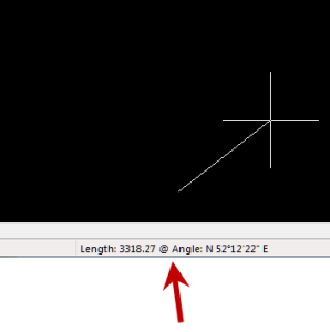
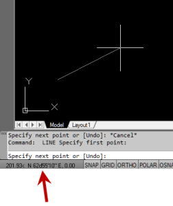
The image below on the left shows the polar coordinate display in AutoCAD and the IntelliCAD version is shown below on the right:

IntelllliCAD Coordinate DisplayAutoCAD Coordinate Display


To toggle the coordinate display in newer versions of AutoCAD (since 2009?) double-click on the coordinate display. In older versions of AutoCAD and in IntelliCAD, the F6 button toggles the display.


Did you know… How easy it is to spruce up your dimensions?

Anyone who has worked with AutoCAD for any length of time can usually create a standard dimension object. However, if you pay close attention to two items in the Object Properties dialog box, you can get very creative with the way simple dimensions are displayed.

For instance, in the image just below, you can see that there are two Object Properties items highlighted in yellow. One is the “Measurement” and the other is the “Text override”. The Measurement is the measured distance between the dimension definition points (DEFPOINTS) and is read-only. You can also see that the current value for Text override is “< >”. Whenever the less-than and greater-than signs are shown as the Text override value, the Measurement will be substituted for the symbols when displayed in the drawing.

Dimension Example

To add just a little more detail to the dimension, you can add descriptive text before or after the “< >” in Text override as shown in the next example below. As long as you keep the “< >”, the correct measured distance will always be displayed as part of the dimension text:

Dimension Example 2And, making it fancier… In the example below, I have added a “P” between < > and “9 SPACES”. This is like pressing Enter to go to a second line and has the effect of stacking two lines of text above the dimension line:

Dimension Example 3

And, finally, one more option. Rather than entering “P”, if you enter “X” as part of your Text override, you will stack the text partially above and partially below the dimension line.

Dimension Example 4The “P” and “X” modifiers can also be used in combination to create 3 or more lines of text and allowing you to control how many lines appear above and how many appear below the dimension line.


IntelliCAD Webinar – Do Over

Last week I presented a webinar sponsored by Carlson Software on the topic “Updates and Overview of IntelliCAD 7”. Unfortunately we had some technical difficulties and didn’t get a complete recording to post to the Movies collection on Carlson’s website.

For those who are interested, we will be re-doing the webinar on Thursday, March 29th. By that time we expect to have additional updates and improvements to announce.

Keep an eye on this site to register for the next IntelliCAD webinar

You can register for these future webinars by clicking the link below:


Did you know… About the “Mid Between 2 Points” OSnap?

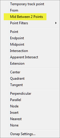
It hasn’t been around forever, but this Object Snap is such a handy little tool you’ll wonder how you ever managed to live without it! The best news is that it’s available both in AutoCAD and IntelliCAD.

Whenever you’re prompted to “Specify a point:”, you can enter “M2P” at the Command: line or you can hold your shift key + right-mouse to display the pop up box and select “Mid Between 2 points” option. This allows you to snap to the MidPoint between two other points. The pop up box is shown below.

Mid Between 2 Points


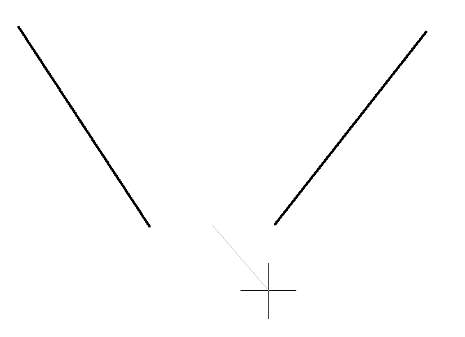
Next you’ll be prompted to specify two new points for which you can use additional OSnap settings. The example below shows a new line that starts at the Midpoint between the ENDpoints of the two existing lines.Finding the MidPoint Between Two ENDpoints