Picks and Clicks: The Key to Standardizing Annotation in CAD Files

This article originally appeared in the June 2011  issue of Professional Surveyor magazine.

Part 1

The issue of CAD standards has long been one of my pet projects when working with clients. It’s the universal problem, as folks from every office confess that CAD standardization is either “non-existent” or, at least, “could be better.”

In my experience, the single most-intimidating aspect to developing a CAD standard is deciding how to standardize annotation in order to accommodate the multiple scale factors used in a typical plan set. Other types of sheets surveyors and civil engineers may have to produce are:

  • a cover sheet (at 1:1 or no scale),
  • one or more project or phase site plan sheet (at 1:50, 1:100, 1:500, 1:1000, etc.),
  • plan and profile sheets (at 1:30, 1:50, etc.), and
  • detail sheets (at 1:1 or no scale).

It’s not an easy issue to resolve, and CAD programs seem to vary from bad to worse in their ability to manage multiple scales within a single CAD file.

Some of the information provided here is very basic, but in my experience even long-time CAD users struggle a bit with the “under-the-hood” details about annotation sizing. So, that being said, where should you start?

Determine the Plotted Size, Plotted Height, Plotted Distance … of Everything

The most important first step when developing a CAD standard for annotation is to determine the desired plotted size of annotation entities. And, when we discuss annotation, we must remember that this encompasses more than just text; it also means linetype patterns and dimension styles.

Here are several sample questions to ask when developing a CAD standard for annotation:

  • When plotted, what is the height (in inches) of the text displaying:

– the project title in the title block?

– the road name?

– contour labels?

– 
property line bearings and distances?

  • When plotted, how far off the property line (in inches) should the bearing and distance label be placed?
  • When plotted, what is the distance (in inches) between labels along a contour?
  • When plotted, what is the length (in inches) of the arrowheads at the end of dimension objects?
  • When plotted, what is the distance (in inches) that the extension line extends beyond the dimension line?
  • When plotted, what is the length (in inches) of the dashes and gaps in the linetype used to show existing contours?

Overwhelmed yet? Don’t be. Once you commit to the size or height of a few entities, the rest come fairly easily just because you know that you want one entity a little smaller or a little bigger than another.

The remainder of this column covers the issue of standardizing text sizes in your CAD files. Future columns will cover the other questions relating to linetypes and dimension styles in much more detail.

Standardizing Text Sizes and Placement

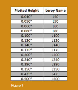
Although text height can be set to any desired value, the most commonly used height for plotted text in civil/survey drawings is 0.08”. There are several other standard text styles (corresponding to the height of the plotted text), known as “Leroy,” that have been adopted from the days of hand and technical lettering. Even though the “Leroy” text style usually has a Simplex font, the naming convention is widely accepted to describe text of a specific height regardless of its font.  For instance, L80 text refers to a Leroy style text that plots 0.08” high; L100 is Leroy with a plot height of 0.10”; and L200 is Leroy with a plot height of 0.20”. Other standard heights and style names are shown in figure 1.

L80, or text that plots 0.08” high, is generally used for basic text such as bearings and distances, contour labels, and notes. For more prominent text such as road names or parcel numbers an L150, or text plotting 0.15”, may be used.

You may be saying, “Yeah, that’s great and all, but when I enter text it asks me for the height of the text to be placed in the drawing, not its plotted height.” If you use the generic commands for placing text, that is true. However, most civil/survey programs have specialized commands for labeling that also take into account a horizontal scale that you specify independently for each drawing.

For instance, in Carlson Software or Civil 3D, you can specify program defaults so that bearing and distance labels always have a plotted height of 0.08”. Then, as each new drawing is started, you set its horizontal scale. For a drawing with a horizontal scale set to 1”=50’, the bearing and distance labels will be placed in the drawing at a height of 4.0’ (0.08 x 50 = 4.0). For a drawing with a horizontal scale set to 1”=100’, the bearing and distance labels will be placed in the drawing at a height of 8.0’ (0.08 x 100 = 8.0). The plotted height never changes.

Consider what a written standard for annotation would look like if we did not base the standard on the plotted size but on the actual drawing size of text…

  • In all 50-scale drawings, bearing and distance labels shall be placed in the drawing at 4.0’ high.
  • In all 100-scale drawings, bearing and distance labels shall be placed in the drawing 8.0’ high.
  • In all 50-scale drawings, all property corner labels shall be placed in the drawing 3.0’ high.
  • In all 100-scale drawings, all property corner labels shall be placed in the drawing 6.0’ high.
  • Unless otherwise specified, all other text in a 50-scale drawing shall be placed in the drawing 4.0’ high.
  • Unless otherwise specified, all other text in a 100-scale drawing shall be placed in the drawing 8.0’ high.

Now, with the understanding that all annotation sizes must be scaled by the horizontal scale, we can simply say:

  • All road names shall be L150.
  • All property corner labels shall be L60.
  • Unless otherwise specified, all other text shall be L80.

As you can see, because the text sizes refer to a plotted height, it makes the writing of CAD standards for annotation remarkably easier.

It is also important to note that, when placing text in a drawing, parameters other than text height can be adjusted to get the desired look. One of these 
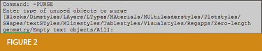
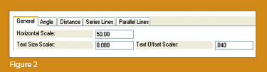
parameters is the distance a label is placed above or below the line it labels.  Figure 2 shows a clip of the Annotate Defaults dialog box in Carlson Survey 2011.

The text height is specified using the “Text Size Scaler” value, and the distance that text is offset from the line it labels is specified by the “Text Offset Scaler.” Both of these values are “plotted” distances in inches. You can also see the horizontal scale setting for the drawing. Once plotted, text placed using these settings will be 0.08” high, and it will be positioned 0.04” off the line. A good rule of thumb is to set the offset value at one half the text height.

Another example of an annotation standard that can be associated with a plotted distance is how far apart to place elevation labels along a contour. Rather than specifying that contour labels are “300’ apart in a 50-scale drawing” or “600’ in a 100-scale drawing,” your standard should state that: On the plotted sheet, contour labels shall be shown at 6” intervals along each index contour.

I hope this information has provided a good kick-start toward your CAD standardization goals and helps get you thinking in plot sizes rather than drawing sizes. As noted above, future columns will focus on other supposed standardization nightmares such as dimension styles and will also touch on some specifics of the different CAD programs. Please don’t hesitate to contact me if you have questions. I hope your summer is off to a great start!

This article originally appeared in the June 2011 issue of Professional Surveyor magazine.


Picks and Clicks: Conquer Problem Drawings

This article originally appeared in the February 2011  issue of Professional Surveyor magazine.

While working with IntelliCAD, AutoCAD, or any other AutoCAD-based programs, we’ve all 
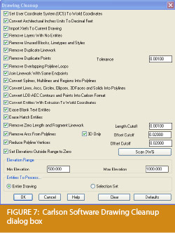
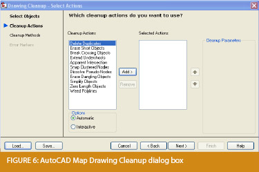
encountered the proverbial drawing from “you-know-where” that seems to drive us crazy from start to finish. Here I offer several tips to help you identify problems and conquer your problem drawings. I’ve listed these tips in the order I would apply them.

1 Purge your drawing.

The PURGE command removes any unused layers, linetypes, text styles, shapes (for linetypes and text), and many other items in the drawing.

When you run the purge command once, it will purge those items that are not currently in use and that have no other dependencies. For example, if a particular linetype definition depends on a particular shape, the purge command will delete the linetype definition only on the first pass.

Purging again will now delete the shape because the dependent linetype no longer resides in the drawing. Enabling the option to “Purge nested items” before purging will automatically execute the command repeatedly until all unused and dependent items are gone.

2 Purge remnants of registered applications that have accessed your drawing.

Typing “–PURGE” will execute the command line version of the purge command. This version includes a few options not available from the purge dialog box.

One of the extra options is “Regapps,” which is available only from the command line version of the command. You access it by typing “R” when prompted. This option removes “leftover” data from other programs (registered applications) that have been used to work on the drawing file.

3 Audit the drawing.

The AUDIT command looks for discrepancies between the objects displayed on the screen and the objects’ definitions in the drawing file database. The command then gives you the option of correcting the errors it has found. This command can be executed only while the drawing is open and active.

4 Recover the drawing and all reference files.

The RECOVER command is a more robust version of the audit command and can be used to open drawings that are so corrupt they cannot be opened otherwise.

Starting the recover command prompts you to browse to and select the problem drawing. If the problem drawing is already open and active, recover will prompt you to save changes before reopening the drawing and starting the recovery process.

For drawings that have attached XREFs (external references), use the RECOVERALL command to open and repair the selected drawing plus all dependent XREFs. Note that errors corrected by the audit are not saved back to the XREFs.

5 Block out the drawing contents to a new drawing.

If you suspect a drawing has become corrupt, you can WBLOCK the entire drawing out to another file. After starting the wblock command, set the “Source” option as “Entire Drawing” and provide the location and name for the newly created file.

Note that this command saves only Model Space entities to the new drawing. If needed, use AutoCAD Design Center to transfer layout tabs.

6 Insert the problem drawing as a block into a new drawing.

Using the same principle as above, you can use the INSERT command to bring the Model Space contents of a problem drawing into another drawing. Doing this will reduce or eliminate corruption in the problem drawing.

Make sure to use 0,0,0 as the insertion point and set the rotation angle and scale appropriately.

As with wblock, this command saves only Model Space entities to the new drawing. If needed, use AutoCAD Design Center to transfer Layout tabs.

7 Export drawings from vertical programs to AutoCAD.

Autodesk products such as Land Desktop or Civil 3D create program-specific, proprietary entities such as AEC Contours and AEC Point Objects. These proprietary objects can become corrupt or otherwise create problems when being accessed from standard AutoCAD or another program that doesn’t recognize the proprietary entities.

You can enter the -EXPORTTOAUTOCAD command at the command line to create a new drawing file that strips out the proprietary entities and leaves only standard AutoCAD entities. For instance, a Land Desktop or Civil 3D drawing containing AEC Contour entities will result in elevated polylines with text when exported to Autocad. And a Land Desktop or Civil 3D drawing containing AEC Point entities will result in a block with attributes when exported to AutoCAD.

Note that any AEC Objects will obviously lose their intelligence, but the new drawing can be opened in any version of Autocad.

8 Use DWG TrueView Convert to fix errors and bind XREFs.

DWG TrueView is a free program that you can download from Autodesk’s website. It is most valuable for its ability to convert drawings to earlier versions individually or in bulk. In the Conversion Setup dialog box, you can specify one or more options to clean drawings during the conversion process.

9 Use the Drawing Cleanup command in AutoCAD Map or Carlson Software.

Both AutoCAD Map and Carlson Software provide Drawing Cleanup commands that provide a variety of cleanup tools. In either version, you have the option of performing one or more cleanup tasks on the entire drawing or on only selected entities in the drawing.

Note: Use these commands with caution and apply cleanup options incrementally to avoid making unwanted changes. Also, I recommend making a backup copy of the active drawing before performing this command.

If you use AutoCAD Map, Land Desktop, or Civil 3D, you can access the Drawing Cleanup command from Map ➜ Tools. In Carlson Software, access it from the File menu.

10

I’ve come up with 9 tips that will help you clean up and, maybe, access drawings that have become corrupt. To round out the list and make it an even 10, I’d like to hear from readers to find out what your favorite drawing recovery and cleanup tools are. Please email me at [email protected] and I’ll report in a future column.

This article originally appeared in the February 2011 issue of Professional Surveyor magazine.


What is Carlson up to?

This is a good article about Bruce Carlson and where Carlson Software is planning to go in the future…

Independence All the Way

Originally posted on Carlson Connection by Jennifer Dibona


Export IntelliCAD or AutoCAD DWG files to Google Earth

I’ve recently started using a very cool feature in Carlson Software. The bad thing… it was in the 2009 version and I didn’t even realize it!

I had no idea exporting our DWG files from IntelliCAD or AutoCAD out to Google Earth was so easy.

  1. Download and install Google Earth. You can download it here: http://earth.google.com/
  2. Open any one of your project DWG files that has been positioned at its correct state plane coordinate system.
  3. In Carlson, go to Settings –> Drawing Setup and then select the correct Projection and correct Zone for the project site. If you’re not sure of the Projection, try using “State Plane 83”. This will work for most systems.
  4. Next, go to File –> Polyline File –> Write Polyline File. When prompted for “Polyline File Format”, type “G” for Google. You will be prompted to specify a new filename and save location for a “Google Earth File to Write (.kml)”.
  5. You will then be prompted to select the entities that are to be exported out to the .kml file and viewed in Google Earth. After selecting the entities, press Enter. For this exercise, we only want to see the drawing entities in 2D, so press “N” for “No” when prompted to “Use elevation from drawing in Google Earth [Yes/<No>]?”
  6. Finally, you are then prompted “Would you like to display the file in Google Earth now [<Yes>/No]?”. Press “Y” for “Yes”. Google Earth should automatically launch and zoom into the project location.

In the example shown below and pointed out with arrows, notice how closely the new roads and designed turn lanes match up to the existing roadway. Also, you can see the designed graded slopes perfectly avoiding the tank that is to be preserved during construction.
Not too shabby…

This feature is available in all of the Carlson Desktop products: Carlson Civil, Survey, Hydrology, Construction and TakeOff.

Look for a future post on bringing Google Earth surface data into Carlson Software. Hint: It’s easy too!

Originally posted on Carlson Connection by Jennifer Dibona


Carlson-IntelliCAD GIS Starter Kit from ESRI

Those currently using Carlson with IntelliCAD are eligible for a new “GIS Starter Kit” from ESRI. The Kit includes:

  • ArcGIS ArcView desktop software
  • A copy of the book A to Z GIS: An Illustrated Dictionary of Geographic Information Systems
  • A copy of GIS Tutorial: Workbook for ArcView 9, Third Edition
  • A 10% discount for the ESRI Survey & Engineering GIS Summit ($325 – standard registration price)

To take advantage of the offer, call 1-800-GIS-XPRT (1-800-447-9778) and request the Carlson-IntelliCAD GIS Starter Kit and please have your Carlson Serial Number available.

You can read more about ESRI’s commitment to survey and engineering services by visiting http://www.ESRI.com/engineering.

Originally posted on Carlson Connection by Jennifer DiBona


Working with Land Desktop or Civil 3D Contours in IntelliCAD-based Carlson Programs


If you are working in an IntelliCAD version of  Carlson Survey or Civil and need to bring in surface entities (contours) from a Civil 3D (C3D) or Land Desktop (LDT) drawing, it’s actually very easy to do. However, it’s not necessarily easy to find on your own. And, unfortunately, it’s in a slightly different place depending on whether you’re using the Carlson Survey or Civil menu.

FYI – If you simply try to “Open” a drawing that has AECC Contour Objects with an IntelliCAD-based program, it may look correct, but the entities will only be the dreaded “ACAD PROXY OBJECTS” that have bogus elevations. These are only good to look at… not work with.

Whether you’re using Survey or Civil, the only thing you’ll need is a drawing file (DWG) containing the C3D or LDT contours for the surface. It doesn’t even need to be opened, you just need to have it and be able to find it. (hey, I’m getting old!).

First, start a new drawing in Carlson.

Then, if you’re using Carlson Civil:

  1. Go to the “Surface” menu,
  2. Select  “Import/Export Surface”
  3. Then, select “Convert LDT/Civil 3D Surface Drawing”.

If you’re using Carlson Survey:

  1. Go to the “Surface” menu,
  2. Select “Import/Export Surface Data”
  3. Then, select “Convert Civil 3D Surface Drawing”.

Next, you’re prompted to “Select the LDT/Civil 3D Drawing to Read”. After browsing to and selecting the LDT or C3D file, pick “Open”.

Next, you’re prompted to to “Select Converted Drawing to Write”. This will be a new DWG file containing the converted data. After browsing to a new location and specifying a new file name, pick the “Save” button.

You’ll see the conversion process in the text window. Once finished, you can open the converted drawing.

What you will find in the new drawing are all of the entities from the original LDT/C3D drawing except that any AECC Contour Objects have been converted to elevated PLINEs and LINEs.

The first step you’ll probably want to take after opening the new drawing is to join together all of the contour PLINEs and LINEs. You may want to “Isolate” the layers for the contours first.

Then use the “Join Nearest” command under the “Edit” menu. Like most cases, make sure to have the “Join Only Common Elevations” and “Join Only Common Layers” options selected.

Originally posted on Carlson Connection by Jennifer Dibona


Carlson + ESRI = Wow!


So, how cool is this? 

At the Carlson User Conference this week in Lexington, KY, Brent Jones of ESRI announced a new grant program in coordination with Carlson Software. The program will bring ESRI products to every IntelliCAD-based Carlson program.

Speaking with Brent on Tuesday, he said that a few of the details have yet to be worked out, but Carlson IntelliCAD users should be hearing details in about a month.

Originally posted on Carlson Connection by Jennifer Dibona


Coming in Carlson 2010

I’m not privy to the “official” list of coming updates, but I can share a few things that I know will be in the next release. Most of these come from “wishlist” items I have submitted on behalf of my clients.

The folks at Carlson are welcome to add their 2-cents in the Comments of this post or on Direct From Carlson.

Option for placing building footprint a distance off the building setback line.

Currently, the LotNet command places the building footprint exactly on the midpoint of the building setback line. We heard the request several times to have the option of placing the footprint some distance behind the setback line. It will be in the 2010 release.

C & G Survey

Instead of having two separate survey programs, Carlson will be incorporating C & G as a separate set of menus in Carlson Survey in 2010.

Basic IntelliCAD Menu

If you’re running Carlson on top of an AutoCAD-based program, you have an icon or menu option to switch over to an AutoCAD menu that has basic Draw commands such as line, pline and text and basic Modify commands such as copy, explode and pedit. Although it’s not easy to get to right now, IntelliCAD has a similar set of menus and toolbars. Carlson 2010  stand-alone with IntelliCAD will have a menu item and toolbar icon allowing you to easily switch over to the IntelliCAD menus and then back again to the Carlson menus.

Lookup table of curb slopes for super-elevation transitioning

This new feature will handle curb transitions like those shown in this NC DOT detail drawing.

Originally posted on Carlson Connection by Jennifer Dibona


IntelliCAD Update for Carlson Products – 2/2/2009

 The most recent IntelliCAD Update for Carlson can be found here:

http://update.carlsonsw.com/entov/c2009_icad_post65_install.exe

From Carlson:

It contains the fixes based on user input and crash submissions since we released 6.5.

In particular, the following features and crashes has been addressed or at least a fix has been attempted:


1) Crash on mouse move
2) Crash on save (during exit?)
3) Another update to image engine to correct problems in the last update
4) Crash during printing or redraw after real time zoom
5) Numerous “small” crashes
6) Crashes during drawing opening or saving
7) Right click menu is added for entity modifications ( this requires menu reload and will reset the menus and toolbars). To reload the menu, type MENU and select icadbase.mnu file.
8) Slow autosave/save has been addressed or at least improved.
9) Font mapping problems have been addressed

In case if this patch makes matters worse for you, the older patch is available here: http://update.carlsonsw.com/entov/c2009_icad_6_6_17_41_install.exe . Simply run it to restore to the last version.

Originally posted on Carlson Connection by Jennifer Dibona


Top Myths About Carlson Software

I’m asked many of these questions on a fairly regular basis and thought it was time to look into some of them and provide the fullest answer I could. Where possible, I’ve researched and found the answer myself. In a few cases I had to rely on Carlson representatives to supply the answers.
  
Myth #1  Autodesk stopped working with Carlson in February 2008. 
  
 False. In February 2008 Carlson simply stopped being a reseller of Autodesk products.

In other words, if you want to run Carlson on top of AutoCAD, Map, Land Desktop or Civil 3D, you’ll have to buy it from an Autodesk reseller instead of from Carlson. Carlson remains part of Autodesk’s Developer Network (ADN) and is listed on Autodesk’s partner page. The ADN designation provides tools to developers to help build their products on top of Autodesk products. As a point of comparison, Eagle Point Software is also a development partner of Autodesk.
  
 
Myth #2  Carlson is owned by Autodesk or, (“bonus”-myth) Carlson will be sold to another, larger software company. 
  
 False. Carlson Software was started in 1983 by Bruce Carlson and remains a private, family-owned business. No one can absolutely guarantee the future, but I have heard Bruce Carlson speak many times about the value he places on competition in the marketplace and his belief that the consolidation of many other software companies has come at the expense of the end-user of the software.

Selling out? I don’t see it. But partnering? Yes. Carlson places a great deal of value on working with any company who wants to work with them.   Click on the image below to see the many different programs Carlson imports data from and exports data to.

Carlson Import and Export Options

Myth #3  Because Carlson Software uses basic AutoCAD entities instead of “intelligent objects”, it does not have 3D or dynamic abilities. 
  
 False. Carlson Software uses basic AutoCAD entities so that all drawings produced by their programs can be easily shared with any other DWG- or DXF-compatible program, regardless of version. Carlson has figured out a way to have the dynamic reactions work on basic entities such as lines, polylines and text. One example would be having profiles and storm drain structures automatically adjust their elevation as a centerline alignment is edited and changed along a surface. And, all of this happens without having to fight the dreaded “proxy objects”!  
 
Myth #4  Because Carlson now works on top of Intellicad, it no longer works on top of AutoCAD-based products. 
  
 False. Carlson Software has always worked on top of AutoCAD-based products and, if you listen to Bruce Carlson discuss the issue, hopes to always continue doing so.

In April 2008, Carlson began giving their customers an IntelliCAD-based “stand-alone” copy of their software with every purchase of Carlson Civil, Survey, Hydrology, GIS, TakeOff and other programs. (IntelliCAD is widely described as an “AutoCAD-clone”. You can read more HERE.). This, again, gives more power and options to Carlson users because it allows the user to choose whether to run Carlson on top of practically any version of AutoCAD, AutoCAD Map, Land Desktop, Civil 3D or on top of IntelliCAD.

Also, with their Sight Survey program (launched in 2008), Carlson created their first program to run on top of MicroStation.

At last year’s 25th Anniversary users’ conference, Bruce Carlson stated that Carlson hopes to have their software working on 4 different platforms within the next few years: IntelliCAD, AutoCAD, Microstation and ESRI. 
  
 
Myth #5  Carlson doesn’t have CIVIL “BIM”-ability. 
  
 First, the premise of the statement is incorrect. BIM (Building Information Modeling), by definition, has no relationship to the civil engineering industry. It is architectural in scope and refers to actual buildings and facilities.

However, for several reasons there has been a push to re-define the term BIM to apply to Civil Engineering (in general) and Civil 3D (in particular). When discussing BIM in the context of Civil Engineering, it simply means that a software program has the ability to:

  • design to specific criteria
  • show a great visual representation of all the components of your project in 3D view and
  • dynamically reflect changes to your project.

Can Carlson Software do all that? Absolutely.

Carlson can, and has been able to, produce true 3D models of civil/survey/utility project sites for years. These models can be viewed in 3D and quantities are dynamically updated whenever the model changes.

Because Carlson has strongly served the U.S. mining industry for over 20 years, they long ago developed features for grading, material quantity calculations and surface viewing and visualization to meet the demands of this industry. In fact, the civil industry pales in comparison to the mining industry in regard to these demands.  
 
Myth #6  Carlson has only been developing civil software since 2007. 
  
 False. To make sure I got this right, I asked the folks at Carlson for help and received the following in response:

Bruce Carlson began developing his software for the mining industry in 1983. By 1984, the program was able to extract profiles and cross-sections, calculate volumes and design road profiles. 3D Surface viewing abilities have been available in Carlson Software since the early 1990’s.

Carlson developed the stand-alone Carlson Survey program in 1996 and in 1999 Autodesk contracted to market and sell a version of it called “Autodesk Field Survey”. Autodesk did away with Field Survey after a few years and Carlson migrated most users over to Carlson Survey where it has grown to become a favorite of surveyors.

Various civil features were organized as modules in a package called SurvCADD that was released in 1989. The civil engineering routines were renamed as Carlson Civil in 2006.

The first Hydrology module for Carlson was released in 1993. It was re-packaged as Carlson Hydrology in 2006.

Carlson Hydrology was the first and, I believe, is still the only H & H software to function entirely within the DWG-environment. If I learn differently after this document is made public, I will post a correction in this space.
  
 
Myth #7  Carlson may have found a spot in some surveying firms, but larger firms aren’t using it. 
  
 False.  Again, I requested generic customer data from Carlson and was told that,

Among our 30,000+ users, there are many DOT agencies and also ENR Top 50 firms using Carlson Software. Carlson Software is very experienced in working with large firms, due to their mining background. All 20 of the top 20 U.S. coal companies use Carlson Software at some level, most being standardized on the software for mine planning and design.

As far as my personal experience, I’ve only been working with Carlson Software for a couple of years and companies I work with tend to have fewer than 25 users. I can personally say that I have seen or know of a few large firms who have moved to or are in the process of moving to Carlson.

These do not include the many customers of mine who have recently let their software contracts lapse, purchased one or more seats of Carlson and have told me they plan to purchase and implement Carlson when the economy rebounds. 
  
 
Myth #8  Carlson Software does not support the full project lifecycle – Concept to Completion. 
  
 False. I think Carlson probably has the project lifecycle covered better than any other software firm in existence.

Carlson Software has data collection, survey processing, civil design, hydrology, GIS, construction material takeoff and machine control software in their stable. 
  
 
Myth #9  Carlson Software doesn’t have the support system in place to adequately support its users. 
  
 False. Carlson provides free technical support directly out of their Maysville, KY and Boston, MA offices. Again, I have heard Bruce Carlson say that keeping tech support free and in-house ensures that their software will remain easy-to-use and that the company will always be responsive to the wishes of their customers.

If a bug or other problem with the software is encountered and logged into Carlson’s tech support department, the corrected files will be emailed to you as soon as the programmers develop the fix. Periodically a collection of the updated files will be released to all users as a maintenance patch. These updates are available to all users whether or not they are under a maintenance contract with Carlson.

I received this testimonial from a customer on March 13, 2009.

“Recently I found that the Time of Concentration input boxes were inadequate under the hydrology portion of Carlson Civil Suite so I emailed a description of the problem to them. I was very impressed to get a phone call the same day. They discussed the problem with me and had a revised program update to me in under a week. I’ve been emailing Autodesk for over a year on problems with Civil 3D and never heard a peep. Needless to say I’m very happy with the customer service I have received from Carlson thus far.”

David Farina, CCAD Engineering
– Greenville, SC

Other examples of Carlson’s responsiveness:

Example 1: The ability of the Carlson Civil & Hydrology “Design Bench Pond” command to have multiple interior benches was added to the software after an attendee at a workshop I held in Raleigh, NC in December 2007 requested it.

Example 2: In the LotNet command, the prompts asking users to specify minimum and maximum building offset distances for lot layout generated too many tech support calls. In the next release, the prompts were re-worded to make the intent more clear.

Example 3: The LotNet command now allows you to designate “sub-areas” (such as wetlands, stream buffers, poor soils, etc.) to be excluded from your area to be subdivided during the lot layout routine. This request came from a prospect during a demonstration in Raleigh.

Example 4: I understand that Carlson’s tech support team was bombarded by requests to change the default cul-de-sac location from the “Start” of the road to the “End” of the road in the RoadNet command. This was changed in the 2009 release.

Example 5: The ability to draw multiple building pads inside lots during the lot layout routine in LotNet was requested by a firm out of Savannah, GA. 
  
 
Myth #10  Carlson Software can’t share data with Land Desktop or Civil 3D. 
  
 False. Carlson has many tools in their software to import civil/survey data from and export data to Land Desktop and Civil 3D. It can be said that Carlson Software works with Civil 3D data as well as Land Desktop or any other civil/survey software and also works with Land Desktop data as well as Civil 3D or any other software.

Carlson has LandXML import and export functionality, can directly convert Land Desktop points and contours into Carlson points and contours and also imports a Civil 3D surface as elevated contours.

Regardless of the civil/survey software being used, LandXML is the best mechanism to import/export a surface model because it maintains the TIN lines of the surface. 
  
 
Myth #11  To be continued. 
  
 If anyone thinks of other question(s) they’d like to supply, please email me HERE. I’m open to suggestions and don’t mind expanding beyond 10 Myths.

Originally posted on Carlson Connection by Jennifer Dibona