Thank you to the Richmond AutoCAD Manifest (RAM)

I’d like to thank Art Thomas and the Richmond Virginia AutoCAD User Group for inviting Jeremy and me to demonstrate Carlson Software and data collection last night. Our hour-and-a-half long presentation covered the basic tools and Survey, Civil and GIS specific features of the Carlson products.

The RAM User Group has been active for 20+ years and has a lot to offer CAD users in the central Virginia area. Their meetings are usually on the 3rd Wednesday of each month and start after work at 5:30. If you’re based in the Richmond area, I’d highly recommend that you join up with them.


Picks and Clicks: Field to Finish Follow Up

This article originally appeared in the December 2011 issue of Professional Surveyor magazine.

After we published “Understanding Field to Finish” in the September issue, I received more feedback and questions than I had for any other article to date. Although my plan for this month’s column had been “CAD Standards Part 2” (Part 1 is in the June issue), it makes more sense to answer some of the questions that were sent my way about Field to Finish first.

(I am using Carlson Survey for the examples in this article, but corresponding features and commands should be available as part of the Field to Finish feature of most other programs.)

The majority of readers’ questions revolve around how to code field descriptions and generate linework for multiple point codes. You use multiple point codes when you have a single field shot that defines more than one feature—for instance, a shot that locates both an edge of pavement and a sidewalk. However, before diving too quickly into multiple point codes, let’s make sure we have a good understanding of the different ways that you can use descriptions and linework codes to generate linework.


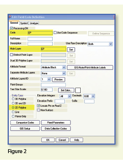
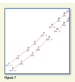
In Figure 1, the dotted lines represent the actual edges of pavement that exist in the field. Points 1-10 have a description “EP” designating them as Edge of Pavement.

When locating features that are generally symmetrical and that have two “sides,” such as a road, a sidewalk, or even a ditch having two tops of bank, we have a choice in how best to collect the points. Depending on field (and traffic) conditions, it may make more sense to take all the shots along one side of the road before crossing the road and taking all the shots along the opposite side.

The other way to collect shots is in what we call Zorro fashion: where we crisscross the street, taking shots on both sides, as we progress down the road. You can see that we used the Zorro style when taking shots in Figure 1. Point 1 is on the northwest side of the road, and shots 2 and 3 are on the southeast side. We then crossed back over to the northwest side to pick up 4 and 5, and so on.

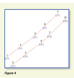
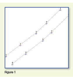
To draw the linework for the edges of pavement, you must create a field code for the EP description. You can see from Figure 2 that it requires only a couple of specific settings to indicate that this is a 2D polyline type of entity and on what layer the polyline is to be created.

With the EP field code defined, using Field to Finish to draw points 1-10 generates the linework on layer “EP” (shown in red in Figure 3). Obviously this is not quite what we expected. I like to say that this is an example of the software doing exactly what we told it to do … rather than what we meant to tell it to do. So, we need to make a couple of adjustments.

The software understands only that it’s expected to connect all of the EP points with a 2D polyline. Carlson Survey allows you to choose whether the field code points are connected in “Sequential” order or “By Nearest Found.” The default setting is “Sequential,” which is why it connected the points the way it did. Unless we provide a little more information, there is no way for it to differentiate one edge of our pavement from another. If we make a minor change in the descriptions we use, we can have the program generate the linework correctly.

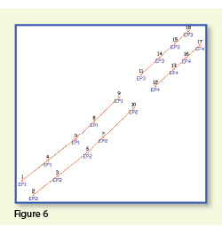
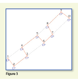
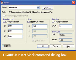
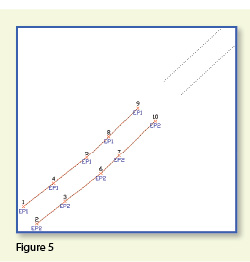
Rather than calling all edge of pavement points EP, we can use a number to modify the description so that we can tell the two polylines apart. We can use “EP1” for the northwest side and “EP2” for the southeast side. Now, when we redraw the points using Field to Finish, we end up with Figure 4, which is exactly what we wanted.

It is important to note that the field code does not change even though we’re now using EP1 and EP2 instead of EP. The field code is still “EP.”

Let’s introduce just a little more complexity. Beyond points 1-10, we have an extension of this road with two additional edges of pavement that are shown as dotted lines in Figure 5. We do not want to continue the linework from points 9 and 10 but to start new polylines instead.

If we use descriptions EP1 and EP2 for the new edges of pavement, Field to Finish will assume we are continuing the other edges of pavement. So we must, again, have a way to differentiate the new edges of pavement from the ones drawn previously.

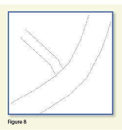
Using the same method as in the prior example, we can use descriptions “EP3” and “EP4” for the new edges of pavement. As you can see in Figure 6, this leaves us with the four separate polylines that we wanted.

The only drawback here is that the numbering of each distinct edge of pavement could get confusing on a large site. In this example, once they’ve been used, EP1 or EP2 can’t be used again without Field to Finish thinking all the EP1 points are part of the same polyline.

The good news is that it only requires another small coding difference to allow you to re-use EP1 or EP2 again. In Figure 7, we still use the EP1 and EP2 descriptions, but we use them in combination with special linework codes “+7” and “-7.” In Carlson lingo, “+7” is the default code to “Start a new polyline” and “-7” is the code to “End the polyline.” You can see that once we have descriptions “EP1 -7” and “EP2 -7” at points 9 and 10, we start new polylines by reusing EP1 and EP2 at points 11 and 12. As long as you’re diligent about using the “-7” special linework code to end the previously drawn polyline, you can reuse the descriptions.

Multiple Point Codes

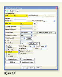
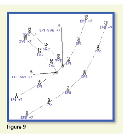
You use multiple point codes when you have two site features (such as the edge of pavement and a sidewalk) that intersect. As you can see in Figure 8 there are two points where a sidewalk meets the edge of pavement. In Figure 9, you can see the descriptions we used so we could have Field to Finish process points 5 and 6 as part of both the EP and SW linework entities.

Point 5’s description “EP1 SW1 +7” means that this shot is a vertex along the current EP1 polyline and also starts a new polyline named SW1 to define the edge of the sidewalk. Point 6’s description “EP1 SW2 +7” means that this shot is also a vertex along the current EP1 polyline and starts another new polyline named SW2 for the other side of the sidewalk.

To have Carlson’s Field to Finish process these points as shown, we had to create only one additional field code: the “SW” code for sidewalk. We set the Entity Type to 2D Polyline and set the Main Layer to “SW” (Figure 10).

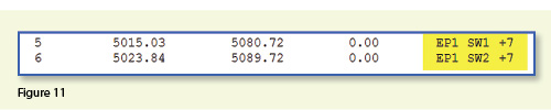
Now, let’s take a closer look at the descriptions for points 5 and 6 (Figure 11). In Carlson Survey, if you use a space between two descriptions, the program allows you to process them separately using the two corresponding field codes. The corresponding field codes used to process these descriptions are EP and SW so Carlson will process the same point twice, first using the EP field code and then again using the SW field code.

Because having a space in a point description is an indicator to Carlson that multiple field codes may need to be processed, it is a best practice to avoid using spaces in your descriptions. Using a description such as 24” RCP PIPE can create several problems, but the main one is that Carlson will think it is supposed to process three separate field codes: one for 24”, one for RCP and one for PIPE. A better description would be PIPE/24” RCP. In this example, a field code named PIPE would be processed. And, because a forward-slash (/) separates PIPE from 24” RCP, Carlson considers everything after the slash as a comment and will ignore it when processing Field to Finish.

If you follow the maze of dialog boxes in Figure 12, there are several settings to take note of:

  • In the Code Table Settings dialog box, there are three possible settings for Split Multiple Codes.
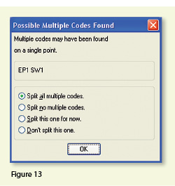
  • If you select “All,” any point description that contains a space will be processed as a multiple point code. If you select “None,” all spaces will be ignored when it comes to processing multiple point codes. If you select “Prompt,” you will be prompted with the dialog box from Figure 13 each time a space is encountered in a point description.
  • In the Code Table Settings dialog box, select the option to “Use Multiple Codes for Linework Only.” This causes Carlson Survey to create both the EP and SW linework on their respective layers but only one point (created on the layer specified by the first field code). If you do not select this option, the program will create two points with the same point number but with different descriptions. Each point will be inserted on the layer specified by its respective field code.

In the Special Codes dialog box, you can see the default settings and are able to customize the Special Codes used to process descriptions, points, and linework in Field to Finish.

With that, I hope I’ve been able to answer a few more of your Field to Finish questions. Please don’t hesitate to call or email as needed. I hope everyone has a fantastic holiday season, and I’ll see you back here in 2012!

This article originally appeared in the December 2011 issue of Professional Surveyor magazine.


Picks and Clicks: Conquer Problem Drawings

This article originally appeared in the February 2011  issue of Professional Surveyor magazine.

While working with IntelliCAD, AutoCAD, or any other AutoCAD-based programs, we’ve all 
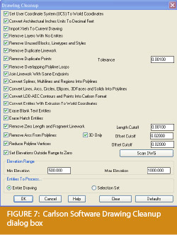
encountered the proverbial drawing from “you-know-where” that seems to drive us crazy from start to finish. Here I offer several tips to help you identify problems and conquer your problem drawings. I’ve listed these tips in the order I would apply them.

1 Purge your drawing.

The PURGE command removes any unused layers, linetypes, text styles, shapes (for linetypes and text), and many other items in the drawing.

When you run the purge command once, it will purge those items that are not currently in use and that have no other dependencies. For example, if a particular linetype definition depends on a particular shape, the purge command will delete the linetype definition only on the first pass.

Purging again will now delete the shape because the dependent linetype no longer resides in the drawing. Enabling the option to “Purge nested items” before purging will automatically execute the command repeatedly until all unused and dependent items are gone.

2 Purge remnants of registered applications that have accessed your drawing.

Typing “–PURGE” will execute the command line version of the purge command. This version includes a few options not available from the purge dialog box.

One of the extra options is “Regapps,” which is available only from the command line version of the command. You access it by typing “R” when prompted. This option removes “leftover” data from other programs (registered applications) that have been used to work on the drawing file.

3 Audit the drawing.

The AUDIT command looks for discrepancies between the objects displayed on the screen and the objects’ definitions in the drawing file database. The command then gives you the option of correcting the errors it has found. This command can be executed only while the drawing is open and active.

4 Recover the drawing and all reference files.

The RECOVER command is a more robust version of the audit command and can be used to open drawings that are so corrupt they cannot be opened otherwise.

Starting the recover command prompts you to browse to and select the problem drawing. If the problem drawing is already open and active, recover will prompt you to save changes before reopening the drawing and starting the recovery process.

For drawings that have attached XREFs (external references), use the RECOVERALL command to open and repair the selected drawing plus all dependent XREFs. Note that errors corrected by the audit are not saved back to the XREFs.

5 Block out the drawing contents to a new drawing.

If you suspect a drawing has become corrupt, you can WBLOCK the entire drawing out to another file. After starting the wblock command, set the “Source” option as “Entire Drawing” and provide the location and name for the newly created file.

Note that this command saves only Model Space entities to the new drawing. If needed, use AutoCAD Design Center to transfer layout tabs.

6 Insert the problem drawing as a block into a new drawing.

Using the same principle as above, you can use the INSERT command to bring the Model Space contents of a problem drawing into another drawing. Doing this will reduce or eliminate corruption in the problem drawing.

Make sure to use 0,0,0 as the insertion point and set the rotation angle and scale appropriately.

As with wblock, this command saves only Model Space entities to the new drawing. If needed, use AutoCAD Design Center to transfer Layout tabs.

7 Export drawings from vertical programs to AutoCAD.

Autodesk products such as Land Desktop or Civil 3D create program-specific, proprietary entities such as AEC Contours and AEC Point Objects. These proprietary objects can become corrupt or otherwise create problems when being accessed from standard AutoCAD or another program that doesn’t recognize the proprietary entities.

You can enter the -EXPORTTOAUTOCAD command at the command line to create a new drawing file that strips out the proprietary entities and leaves only standard AutoCAD entities. For instance, a Land Desktop or Civil 3D drawing containing AEC Contour entities will result in elevated polylines with text when exported to Autocad. And a Land Desktop or Civil 3D drawing containing AEC Point entities will result in a block with attributes when exported to AutoCAD.

Note that any AEC Objects will obviously lose their intelligence, but the new drawing can be opened in any version of Autocad.

8 Use DWG TrueView Convert to fix errors and bind XREFs.

DWG TrueView is a free program that you can download from Autodesk’s website. It is most valuable for its ability to convert drawings to earlier versions individually or in bulk. In the Conversion Setup dialog box, you can specify one or more options to clean drawings during the conversion process.

9 Use the Drawing Cleanup command in AutoCAD Map or Carlson Software.

Both AutoCAD Map and Carlson Software provide Drawing Cleanup commands that provide a variety of cleanup tools. In either version, you have the option of performing one or more cleanup tasks on the entire drawing or on only selected entities in the drawing.

Note: Use these commands with caution and apply cleanup options incrementally to avoid making unwanted changes. Also, I recommend making a backup copy of the active drawing before performing this command.

If you use AutoCAD Map, Land Desktop, or Civil 3D, you can access the Drawing Cleanup command from Map ➜ Tools. In Carlson Software, access it from the File menu.

10

I’ve come up with 9 tips that will help you clean up and, maybe, access drawings that have become corrupt. To round out the list and make it an even 10, I’d like to hear from readers to find out what your favorite drawing recovery and cleanup tools are. Please email me at [email protected] and I’ll report in a future column.

This article originally appeared in the February 2011 issue of Professional Surveyor magazine.


The Power of LandXML

 The ability to import and export to LandXML has been around for quite awhile, but I still get a lot of curious looks when I mention it in my training classes. So, what is it? And why should you be using it?

Why Should We Be Using It?

We’ve all become accustomed to saving archive copies of our drawings for various purposes but saving the corresponding project data is often overlooked. Retrieving the drawing file may allow you to recover proposed contours and profile grid, but the underlying “surface” is lost unless the project was also archived.

Importing and exporting using XML files is the most convenient way to convert, transfer and archive data created in Carlson Software, Land Desktop, Civil 3D, Eagle Point, TerraModel and, I’m sure, other programs.

But, What Is LandXML?

LandXML refers to a file format (.xml) containing data created in a civil/survey program. My recommendation is that ALL civil and survey data should be archived – progress, submittal and final archive – using LandXML.

The way I like to explain it is that we use XML files in the same way we used to rely on DXF files. They’re mostly outdated now, but DXF files are a generic file format that, for example, we used to convert MicroStation DGN files to AutoCAD DWG files. At that time, AutoCAD couldn’t read DGN files and Microstation couldn’t read DWG files; but both could read DXF files. So, we had to convert our drawing files to the generic DXF format that could then be read into the other program.

Similarly, Carlson Software, Land Desktop, Civil 3D and the other programs create their own unique files for civil/survey project data such as points, point groups, surfaces, centerlines, profiles, etc. When we have to pass that data onto someone using a different civil/survey program – it’s a nightmare!

That’s where LandXML files prove their value.

Exporting your civil/survey data to an XML file breaks it all down into, basically, a text file. Specifically, it’s an HTML file that can be viewed through a web browser such as Internet Explorer or Firefox. For instance, when a surface model (TIN) is exported to XML, the X, Y, Z values of each point on the TIN is assigned a number, and then each “face” (triangle) of the TIN is defined by specifying the 3 corners. See the examples below:

xmlpost_01 

xmlpost_02

Note that one type of data that is currently not supported in XML files is typical cross-sections or template files.

Another benefit of using LandXML to transfer or archive project data is that any combination or all of your project data can be saved in a single XML file. This is valuable because exporting ALL of the data for a project can create a massive XML file.

Even if you archive your project data in its native format, you should consider additional archiving in XML format. No one knows what kind data files we’ll be using 10 or 20 years down the road so saving your data in such a generic, text-based format such as XML files allows for easier retrieval down the road.

Originally posted on Carlson Connection by Jennifer Dibona


Working with Land Desktop or Civil 3D Contours in IntelliCAD-based Carlson Programs


If you are working in an IntelliCAD version of  Carlson Survey or Civil and need to bring in surface entities (contours) from a Civil 3D (C3D) or Land Desktop (LDT) drawing, it’s actually very easy to do. However, it’s not necessarily easy to find on your own. And, unfortunately, it’s in a slightly different place depending on whether you’re using the Carlson Survey or Civil menu.

FYI – If you simply try to “Open” a drawing that has AECC Contour Objects with an IntelliCAD-based program, it may look correct, but the entities will only be the dreaded “ACAD PROXY OBJECTS” that have bogus elevations. These are only good to look at… not work with.

Whether you’re using Survey or Civil, the only thing you’ll need is a drawing file (DWG) containing the C3D or LDT contours for the surface. It doesn’t even need to be opened, you just need to have it and be able to find it. (hey, I’m getting old!).

First, start a new drawing in Carlson.

Then, if you’re using Carlson Civil:

  1. Go to the “Surface” menu,
  2. Select  “Import/Export Surface”
  3. Then, select “Convert LDT/Civil 3D Surface Drawing”.

If you’re using Carlson Survey:

  1. Go to the “Surface” menu,
  2. Select “Import/Export Surface Data”
  3. Then, select “Convert Civil 3D Surface Drawing”.

Next, you’re prompted to “Select the LDT/Civil 3D Drawing to Read”. After browsing to and selecting the LDT or C3D file, pick “Open”.

Next, you’re prompted to to “Select Converted Drawing to Write”. This will be a new DWG file containing the converted data. After browsing to a new location and specifying a new file name, pick the “Save” button.

You’ll see the conversion process in the text window. Once finished, you can open the converted drawing.

What you will find in the new drawing are all of the entities from the original LDT/C3D drawing except that any AECC Contour Objects have been converted to elevated PLINEs and LINEs.

The first step you’ll probably want to take after opening the new drawing is to join together all of the contour PLINEs and LINEs. You may want to “Isolate” the layers for the contours first.

Then use the “Join Nearest” command under the “Edit” menu. Like most cases, make sure to have the “Join Only Common Elevations” and “Join Only Common Layers” options selected.

Originally posted on Carlson Connection by Jennifer Dibona


AutoCAD 2010 Release, Autodesk 2006 Software Retirement

Autodesk has announced that their 2010 products will be released on March 24, 2009. I found this post by Randy McSwain to be a good overview of the new features in AutoCAD 2010.

As of March 13, 2009, Autodesk no longer supports or offers upgrades from their 2006 products.

Because of the retirement of Land Desktop, I see that Autodesk is offering to crossgrade existing Land Desktop customers to Map or Civil 3D with special pricing. Subscription will probably be mandatory, but I’m not certain.

Originally posted on Carlson Connection by Jennifer Dibona


BIM this, BIM that… What is BIM?

 Q:     What is BIM? And, exactly how does it relate to the civil engineering industry?

 A:     BIM, by definition, has nothing to do with civil engineering.

BIM stands for “Building Information Modeling”. The term “BIM” originated in the Architectural world and, generally, defines the process of inputting information to and extracting information from a 3D model of a building/facility.

Definition of BIM from the National BIM Standard:

BIM is best thought of as “a digital representation of physical and functional characteristics of a facility…and a shared knowledge resource for information about a facility forming a reliable basis for decisions during its life-cycle; defined as existing from earliest conception to demolition.”

From the National Institute of Building Sciences:

Building Information Modeling (BIM) refers to the use of the concepts and practices of open and interoperable information exchanges, emerging technologies, new business structures and influencing the re-engineering of processes in ways that dramatically reduce multiple forms of waste in the building industry. The National BIM Standard, a key element of the overall industry transformation being supported and coordinated by the buildingSMART alliance™, establishes standard definitions for building information exchanges to support critical business decisions. Implemented in software, the consensus-based standard will form a basis for more accurate and efficient commerce within the capital facilities industry. The National BIM Standard is also intended to help participants in facilities-related processes achieve more reliable outcomes from commercial agreements.

From Geomatics International:

A Building Information Model (BIM) is a digital representation of physical and functional characteristics of a building. Construction and management of buildings involves many stakeholders, so that proper sharing of information over the entire lifecycle of a building is very important. The Open Geospatial Consortium (OGC) is developing BIM standards that promote efficient web-based information sharing in the Architectural, Engineering, Construction and building Ownership and Operation (AECOO) markets.

Because Wikipedia is open-source and able to be edited by anyone and everyone, the entry for BIM changes regularly. The entire entry looked like this as of February 26, 2009. Here is an excerpt:

Building Information Modeling (BIM) is the process of generating and managing building data during its life cycle[1]. Typically it uses three-dimensional, real-time, dynamic building modeling software to increase productivity in building design and construction.[2] The process produces the Building Information Model (also abbreviated BIM), which encompasses building geometry, spatial relationships, geographic information, and quantities and properties of building components.

A lot of confusion is now occurring because Autodesk and their civil resellers are trying to make the connection between BIM and Civil or, more specifically, Civil 3D. See examples here:

BIM for Civil Engineers by Sanjay Asnani, Autodesk
  If link doesn’t work, find this document HERE.

What Does BIM Mean for Civil Engineers? by Adam Strafaci, Autodesk

Civil 3D and BIM… How do they relate? by Melanie Santer, US CAD

However, if you simply Google “bim building information modeling” and look at the first two pages of returns, the only entries that attempt to connect BIM and civil engineering belong to Autodesk or one of their civil resellers. All other hits refer to BIM in an architectural/building sense. If there is a specific software program mentioned, it is Autodesk’s Revit product. A caveat to this is the civil/structural engineering specialty field of bridge construction which can also be modeled using Revit. Bridge construction is a bit of a hybrid in that it is similar to building design and can also legitimately be related to BIM.

Among Autodesk’s architectural team and resellers, most, if not all, references to BIM are solely in an architectural/building capacity. See examples here (pages were cached on 2/26/09):

Brave New BIM

The World According to BIM – Part 1

Summit AEC – Autodesk BIM & CAD Software

As you can see from the above links, it is technically incorrect to connect BIM and Civil. However, many in the civil world are witnessing the Autodesk definition of BIM take hold. So, in the event you are ever asked or required to “BIM” a civil project, you are essentially being asked to design and deliver a dynamic, 3d model of the entire project.

It is important to realize that creating a dynamic 3d model for a Civil project (or “BIM”ing a civil project) is not limited to using a particular software program.

Find a civil engineering design software that allows you to design to specific criteria, is able to show a great visual representation of all the components of your project in 3D view and is able to dynamically reflect changes and you can “BIM” along with the rest of the world.

Designing a project using a dynamic model allows you to design according to specific criteria such as AASHTO (American Association of State Highway and Transportation Officials) standards or by specifying minimum/maximum values for storm or sanitary sewer design. It also is invaluable to detect, before construction, potential conflicts between a proposed network of roads and associated utility networks. As an example, a dynamic 3d model would trigger a warning if, when lowering a roadway, the rule for minimum cover over a pipe on an adjacent roadway has been violated. Also, creating this model allows you to view the model, make changes to vertical alignments and see dynamically updated cut/fill quantities all at once.

To reduce the confusion, it might be time to coin a new term such as “Site Information Modeling” to describe the process in the Civil industry. But, there is still quite a disparity between the “Information Modeling” done for a Building compared to that done for a Civil project. In true BIM, the “I” (Information) component is as important as the “M” (Modeling) component because determining usability and functionality of the Building through its lifecycle is one of the goals of BIM. At this time, the process on the Civil side is still much more about the “Model” and not nearly so much about the “Information” going into and coming out of the model. When we are able to incorporate results of traffic flow analyses for a roadway or inspection reports showing sludge build-up and flow capacities in sewer/storm pipies and manholes, we will be truly using the “Information” as it was intended in an “Information Model”.

Originally posted on Carlson Connection by Jennifer Dibona


Top Myths About Carlson Software

I’m asked many of these questions on a fairly regular basis and thought it was time to look into some of them and provide the fullest answer I could. Where possible, I’ve researched and found the answer myself. In a few cases I had to rely on Carlson representatives to supply the answers.
  
Myth #1  Autodesk stopped working with Carlson in February 2008. 
  
 False. In February 2008 Carlson simply stopped being a reseller of Autodesk products.

In other words, if you want to run Carlson on top of AutoCAD, Map, Land Desktop or Civil 3D, you’ll have to buy it from an Autodesk reseller instead of from Carlson. Carlson remains part of Autodesk’s Developer Network (ADN) and is listed on Autodesk’s partner page. The ADN designation provides tools to developers to help build their products on top of Autodesk products. As a point of comparison, Eagle Point Software is also a development partner of Autodesk.
  
 
Myth #2  Carlson is owned by Autodesk or, (“bonus”-myth) Carlson will be sold to another, larger software company. 
  
 False. Carlson Software was started in 1983 by Bruce Carlson and remains a private, family-owned business. No one can absolutely guarantee the future, but I have heard Bruce Carlson speak many times about the value he places on competition in the marketplace and his belief that the consolidation of many other software companies has come at the expense of the end-user of the software.

Selling out? I don’t see it. But partnering? Yes. Carlson places a great deal of value on working with any company who wants to work with them.   Click on the image below to see the many different programs Carlson imports data from and exports data to.

Carlson Import and Export Options

Myth #3  Because Carlson Software uses basic AutoCAD entities instead of “intelligent objects”, it does not have 3D or dynamic abilities. 
  
 False. Carlson Software uses basic AutoCAD entities so that all drawings produced by their programs can be easily shared with any other DWG- or DXF-compatible program, regardless of version. Carlson has figured out a way to have the dynamic reactions work on basic entities such as lines, polylines and text. One example would be having profiles and storm drain structures automatically adjust their elevation as a centerline alignment is edited and changed along a surface. And, all of this happens without having to fight the dreaded “proxy objects”!  
 
Myth #4  Because Carlson now works on top of Intellicad, it no longer works on top of AutoCAD-based products. 
  
 False. Carlson Software has always worked on top of AutoCAD-based products and, if you listen to Bruce Carlson discuss the issue, hopes to always continue doing so.

In April 2008, Carlson began giving their customers an IntelliCAD-based “stand-alone” copy of their software with every purchase of Carlson Civil, Survey, Hydrology, GIS, TakeOff and other programs. (IntelliCAD is widely described as an “AutoCAD-clone”. You can read more HERE.). This, again, gives more power and options to Carlson users because it allows the user to choose whether to run Carlson on top of practically any version of AutoCAD, AutoCAD Map, Land Desktop, Civil 3D or on top of IntelliCAD.

Also, with their Sight Survey program (launched in 2008), Carlson created their first program to run on top of MicroStation.

At last year’s 25th Anniversary users’ conference, Bruce Carlson stated that Carlson hopes to have their software working on 4 different platforms within the next few years: IntelliCAD, AutoCAD, Microstation and ESRI. 
  
 
Myth #5  Carlson doesn’t have CIVIL “BIM”-ability. 
  
 First, the premise of the statement is incorrect. BIM (Building Information Modeling), by definition, has no relationship to the civil engineering industry. It is architectural in scope and refers to actual buildings and facilities.

However, for several reasons there has been a push to re-define the term BIM to apply to Civil Engineering (in general) and Civil 3D (in particular). When discussing BIM in the context of Civil Engineering, it simply means that a software program has the ability to:

  • design to specific criteria
  • show a great visual representation of all the components of your project in 3D view and
  • dynamically reflect changes to your project.

Can Carlson Software do all that? Absolutely.

Carlson can, and has been able to, produce true 3D models of civil/survey/utility project sites for years. These models can be viewed in 3D and quantities are dynamically updated whenever the model changes.

Because Carlson has strongly served the U.S. mining industry for over 20 years, they long ago developed features for grading, material quantity calculations and surface viewing and visualization to meet the demands of this industry. In fact, the civil industry pales in comparison to the mining industry in regard to these demands.  
 
Myth #6  Carlson has only been developing civil software since 2007. 
  
 False. To make sure I got this right, I asked the folks at Carlson for help and received the following in response:

Bruce Carlson began developing his software for the mining industry in 1983. By 1984, the program was able to extract profiles and cross-sections, calculate volumes and design road profiles. 3D Surface viewing abilities have been available in Carlson Software since the early 1990’s.

Carlson developed the stand-alone Carlson Survey program in 1996 and in 1999 Autodesk contracted to market and sell a version of it called “Autodesk Field Survey”. Autodesk did away with Field Survey after a few years and Carlson migrated most users over to Carlson Survey where it has grown to become a favorite of surveyors.

Various civil features were organized as modules in a package called SurvCADD that was released in 1989. The civil engineering routines were renamed as Carlson Civil in 2006.

The first Hydrology module for Carlson was released in 1993. It was re-packaged as Carlson Hydrology in 2006.

Carlson Hydrology was the first and, I believe, is still the only H & H software to function entirely within the DWG-environment. If I learn differently after this document is made public, I will post a correction in this space.
  
 
Myth #7  Carlson may have found a spot in some surveying firms, but larger firms aren’t using it. 
  
 False.  Again, I requested generic customer data from Carlson and was told that,

Among our 30,000+ users, there are many DOT agencies and also ENR Top 50 firms using Carlson Software. Carlson Software is very experienced in working with large firms, due to their mining background. All 20 of the top 20 U.S. coal companies use Carlson Software at some level, most being standardized on the software for mine planning and design.

As far as my personal experience, I’ve only been working with Carlson Software for a couple of years and companies I work with tend to have fewer than 25 users. I can personally say that I have seen or know of a few large firms who have moved to or are in the process of moving to Carlson.

These do not include the many customers of mine who have recently let their software contracts lapse, purchased one or more seats of Carlson and have told me they plan to purchase and implement Carlson when the economy rebounds. 
  
 
Myth #8  Carlson Software does not support the full project lifecycle – Concept to Completion. 
  
 False. I think Carlson probably has the project lifecycle covered better than any other software firm in existence.

Carlson Software has data collection, survey processing, civil design, hydrology, GIS, construction material takeoff and machine control software in their stable. 
  
 
Myth #9  Carlson Software doesn’t have the support system in place to adequately support its users. 
  
 False. Carlson provides free technical support directly out of their Maysville, KY and Boston, MA offices. Again, I have heard Bruce Carlson say that keeping tech support free and in-house ensures that their software will remain easy-to-use and that the company will always be responsive to the wishes of their customers.

If a bug or other problem with the software is encountered and logged into Carlson’s tech support department, the corrected files will be emailed to you as soon as the programmers develop the fix. Periodically a collection of the updated files will be released to all users as a maintenance patch. These updates are available to all users whether or not they are under a maintenance contract with Carlson.

I received this testimonial from a customer on March 13, 2009.

“Recently I found that the Time of Concentration input boxes were inadequate under the hydrology portion of Carlson Civil Suite so I emailed a description of the problem to them. I was very impressed to get a phone call the same day. They discussed the problem with me and had a revised program update to me in under a week. I’ve been emailing Autodesk for over a year on problems with Civil 3D and never heard a peep. Needless to say I’m very happy with the customer service I have received from Carlson thus far.”

David Farina, CCAD Engineering
– Greenville, SC

Other examples of Carlson’s responsiveness:

Example 1: The ability of the Carlson Civil & Hydrology “Design Bench Pond” command to have multiple interior benches was added to the software after an attendee at a workshop I held in Raleigh, NC in December 2007 requested it.

Example 2: In the LotNet command, the prompts asking users to specify minimum and maximum building offset distances for lot layout generated too many tech support calls. In the next release, the prompts were re-worded to make the intent more clear.

Example 3: The LotNet command now allows you to designate “sub-areas” (such as wetlands, stream buffers, poor soils, etc.) to be excluded from your area to be subdivided during the lot layout routine. This request came from a prospect during a demonstration in Raleigh.

Example 4: I understand that Carlson’s tech support team was bombarded by requests to change the default cul-de-sac location from the “Start” of the road to the “End” of the road in the RoadNet command. This was changed in the 2009 release.

Example 5: The ability to draw multiple building pads inside lots during the lot layout routine in LotNet was requested by a firm out of Savannah, GA. 
  
 
Myth #10  Carlson Software can’t share data with Land Desktop or Civil 3D. 
  
 False. Carlson has many tools in their software to import civil/survey data from and export data to Land Desktop and Civil 3D. It can be said that Carlson Software works with Civil 3D data as well as Land Desktop or any other civil/survey software and also works with Land Desktop data as well as Civil 3D or any other software.

Carlson has LandXML import and export functionality, can directly convert Land Desktop points and contours into Carlson points and contours and also imports a Civil 3D surface as elevated contours.

Regardless of the civil/survey software being used, LandXML is the best mechanism to import/export a surface model because it maintains the TIN lines of the surface. 
  
 
Myth #11  To be continued. 
  
 If anyone thinks of other question(s) they’d like to supply, please email me HERE. I’m open to suggestions and don’t mind expanding beyond 10 Myths.

Originally posted on Carlson Connection by Jennifer Dibona