
FAQ
Faq category: Tips, Tricks & Solutions
SEARCH THAT CAD GIRL SITE
How do AutoCAD, IntelliCAD and BricsCAD compare for raster-to-vector capabilities? (a running thread)
+
This is a running thread. I’ll update it when AutoCAD, IntelliCAD or BricsCAD change what they can do natively with rasters and scans.
First, a quick definition so we’re talking about the same thing. Raster-to-vector conversion means taking a scanned picture of a drawing (pixels) and automatically turning the lines, arcs and text on that scan into real, editable CAD entities (polylines, arcs, text and so on). Attaching an image and tracing over it by hand is not conversion. Importing a vector PDF’s geometry is also not the same thing as converting a scan.
I get asked this a lot when someone has a scanned survey plat, an old topographic sheet or a blurry engineering drawing and wants that linework turned into CAD. So I lined up the three platforms people ask me about most: AutoCAD, IntelliCAD and BricsCAD.
As of October 9, 2026, this comparison is based on AutoCAD 2027, IntelliCAD 15.0 and BricsCAD V26. It covers only the native CAD platforms. It does not include third-party raster-to-vector apps or specialized toolsets. Those tools do exist and they are where the real conversion work happens.
Jump to:
- The comparison table
- What the rows actually mean
- So what do you do with a scanned drawing?
- What about third-party apps?
The comparison table
Here’s the side-by-side. “Yes” means the feature is built into the core platform. “No” means it isn’t.
| Feature | IntelliCAD 15 | BricsCAD V26 | AutoCAD 2027 |
|---|---|---|---|
| Attach raster images (JPG, PNG, TIFF) | Yes | Yes | Yes |
| Scale, rotate and position raster images | Yes | Yes | Yes |
| Manually trace raster drawings | Yes | Yes | Yes |
| Attach scanned PDFs as underlays | Yes | Yes | Yes |
| Import vector PDF geometry as CAD entities | Implementation-dependent | Yes | Yes |
| Automatically convert scanned lines to CAD entities | No | No | No |
| Convert scanned contour lines to polylines | No | No | No |
| OCR recognition of scanned text | No | No | No |
What the rows actually mean
All three platforms let you attach a JPG, PNG or TIFF, then scale, rotate and position it so you can draw over it. That’s the old-fashioned way and it still works just fine.
All three also let you attach a scanned PDF as an underlay. Same idea: the scan sits under your drawing and you trace what you need.
What none of them do natively is look at a scanned picture of lines and turn those pixels into editable polylines, arcs and text for you. No automatic line conversion. No contour-to-polyline magic. No OCR that reads the text off the scan. If you want that, you’re looking at a specialized raster-to-vector tool or a toolset that sits on top of the CAD program.
So what do you do with a scanned drawing?
For scanned survey plats, topographic maps and legacy engineering drawings, all three platforms land in the same place:
- Attach the image or PDF underlay.
- Scale and position it so it matches your coordinate system or known distances.
- Trace the linework you actually need… or run the scan through a dedicated raster-to-vector program first, then bring the resulting CAD entities in.
In other words, don’t pick AutoCAD, IntelliCAD or BricsCAD expecting a built-in “turn this scan into CAD” button. Pick them for the CAD work. Handle the conversion with a specialized tool when the volume of tracing would make you crazy.
What about third-party apps?
Yes, there are third-party apps (and a few specialized toolsets) that actually do raster-to-vector conversion. They are built for that job: reading scanned linework, cleaning it up and turning it into editable CAD geometry, sometimes with OCR for the text.
If conversion is a big part of your workflow, look at those tools separately. The comparison table above is about what the three CAD platforms themselves can and cannot do without that help.

Some content on this website was prepared with AI assistance. Please verify important information with the manufacturer or original source before making purchasing or financial decisions.
If you find the material on this website helpful, please consider supporting That CAD Girl by purchasing our products or services.
If you are interested in purchasing products or services we do not offer, we would love to refer you to one of our Trusted Partners. Please click here to send us a message with your request.
How Does BricsCAD Handle GIS and Online Map Services?
+This post covers BricsCAD Pro V26. We’ll update it when BricsCAD V27 comes out.
As of October 8, 2026, the current release is BricsCAD V26.2.08 (September 15, 2026).
Short answer: yes! BricsCAD can pull in imagery from public map servers, show online maps behind your linework, attach your own georeferenced aerials and bring GIS data in and out with its attributes.
But if you’re looking for Bing maps, here’s the scoop… Bing Maps have been retired and can no longer be used in BricsCAD. The good news is that OpenStreetMap is free and needs no key, Esri maps work with an Esri API key (Free*) and BricsCAD Pro can connect to a Web Map Service (WMS).
* The Esri API is free up to a point. See Getting an Esri map key for the monthly tile limit and what happens after that.
Jump to:
- Can BricsCAD link to open source or government map services?
- First things first: set your geographic location
- Online maps with GEOMAP
- Getting an Esri map key
- Capturing a map image
- Importing and exporting GIS data
- Attaching your own georeferenced images
- What’s in Lite and what needs Pro?
Does BricsCAD allow users to link to open source or government services such as feature services or map services?
Yes. BricsCAD supports connecting to Web Map Service (WMS) endpoints using the MAPCONNECT command (BricsCAD Pro and higher), which lets you add map imagery from public and government-hosted WMS servers into your drawing.
Before adding WMS data, you must set the drawing’s geographic location using GEOGRAPHICLOCATION (more on that below). Then:
- Create the connection – give it a name, the server URL and version, plus a login if the server needs one.
- Pick your layers – select one or more data layers, set the ground resolution and the maximum tile size and check the estimated download size before you click Add.
BricsCAD saves the downloaded map tiles as regular image files in the same folder as your drawing, so keep that in mind when you send the drawing to someone else.
For vector GIS features with attributes, the other half of that question, see Importing and exporting GIS data.
First things first: set your geographic location
Everything map-related starts with GEOGRAPHICLOCATION (you can also type GEO, NORTH or NORTHDIR). It opens the Geographic Location dialog box, where you pick a GIS coordinate system or add coordinates manually. Under Advanced / BIM Settings you can:
- Set the real-world location of the geographic marker in decimal latitude and longitude, in degrees, minutes and seconds or as a projected Easting and Northing, plus an elevation.
- Set the marker’s position in the drawing by typing X, Y and Z values or picking a point.
- Set the north direction, which is saved to the NORTHDIRECTION system variable.
- Remove the geographic location data if you need to start over.
The GIS Coordinate System button on the status bar opens the same dialog. And for the CAD managers writing scripts or LISP, there’s a command line version: -GEOGRAPHICLOCATION.
Online maps with GEOMAP
BricsCAD also supports displaying online maps inside a drawing using GEOMAP. Your choices are:
- open street Map – free to use and doesn’t require an API key.
- esri Imagery, esri Streets, esri Light, esri Dark and esri Hybrid – available only when an Esri API key is assigned. Hybrid combines the aerial imagery with labels.
- Off – hides the map.
What about drawings that were set up with Bing? By default, BricsCAD substitutes them automatically: Bing Aerial becomes esri Imagery, Bing Road becomes open street Map and Bing Hybrid becomes esri Hybrid. You’ll see a notification in the lower right corner when that happens.
So… what is OpenStreetMap? Think of it like Wikipedia, but for maps! OpenStreetMap is a free world map built and kept up to date by volunteers all over the world. They add the roads, buildings, trails, rivers and place names, and anyone can use it for free. That’s why BricsCAD can give it to you with no key. Just keep in mind that it’s a street-style map, not aerial photos. If you want imagery, you’ll need one of the Esri styles. (Techie tip: the GEOMAPOSMMODE system variable controls where the open street Map tiles come from. The default of 1 uses OpenStreetMap’s own maps and 0 switches to Esri’s version.)
The map’s copyright and watermark show in the lower right corner of the drawing area, and you’ll see a downloading message while the map tiles load.
Getting an Esri map key
Run GEOMAPKEY to open the Online Maps Support dialog box and paste your Esri key into the Esri Key field. You create the key yourself with a free account on Esri’s ArcGIS Location Platform, giving it the Basemaps privileges (both Basemap styles service and Static basemap tiles).
Here’s the kicker… according to the BricsCAD help as of October 8, 2026:
- Free tiles – the first 2 million map tiles per month are free.
- After that – it’s $0.15 per 1,000 tiles. If you go over the free limit, the maps stop working until you turn on pay-as-you-go in your Esri dashboard or buy a voucher.
- One key per person – BricsCAD recommends that each user create their own Esri account and key to stay under the limit.
- Keys expire – the default is 90 days and the maximum is one year. After that you’ll need to generate a new key.
Esri sets that pricing, so it can change. My advice? Put a reminder on your calendar for the day your key expires!
Capturing a map image
GEOMAPIMAGE captures a rectangle of the online map (or the whole current viewport) and embeds it in the drawing as an image. A frame shows where the capture is, and if you change the frame’s size or position, the image updates. Run GEOMAP again and choose Off if you want to see only your captured image. The copyright and watermark are added to the bottom right corner of the image.
Then fine-tune it with:
- GEOMAPIMAGETYPE – changes the map style of the captured image.
- GEOMAPIMAGERESOLUTION – sets the resolution to Coarse, Optimal, Fine or VeryFine.
- GEOMAPIMAGEUPDATE – optimizes or reloads the image.
Importing and exporting GIS data
For importing vector GIS data as CAD entities with attributes, BricsCAD Pro provides:
- GISIMPORT – imports vector GIS features with their original location, shape and attributes from SHP, GML, KML/KMZ and Esri Geodatabase files. Features come in as points, lines and polylines on the drawing layers you choose, only inside the import area you set and with coordinate system transformation.
- GISEXPORT – exports vector GIS features with their location, shape and attributes to SHP, GML or KML/KMZ files.
- GISCONVERT – converts Object Data and Mpolygons in a drawing you’ve received into BricsCAD GIS data. CONVERTGISTOOBJECTDATA goes the other way and turns BricsCAD GIS data into Object Data.
- MPOLYGON – creates multi-sided polygon entities, handy for GIS polygons with holes and islands.
- MOVEBLOCKSTOELEVATION – moves each block’s insertion point to the elevation in its block attribute or GIS data.
- GEOIMPORT – imports a DWG or DXF drawing and places it based on the geographic location of both the source and target drawings.
Civil labels can also display GIS attributes, and point clouds with geographic data can set your drawing’s location (see our point cloud FAQ below).
Attaching your own georeferenced images
Have an aerial from your county or a drone flight? Attach it with IMAGEATTACH (alias IAT). In the Attach Raster Image dialog box, turn on Use Geocoding Information and BricsCAD uses the image’s position file (world file) to set its size, location and rotation for you.
What’s in Lite and what needs Pro?
Good news for Lite users: the online map basics are included in every edition.
- Included in Lite and Pro: GEOGRAPHICLOCATION, GEOMAP, GEOMAPKEY, GEOMAPIMAGE, GEOMAPIMAGETYPE, GEOMAPIMAGERESOLUTION, GEOMAPIMAGEUPDATE and IMAGEATTACH.
- Requires Pro or higher: MAPCONNECT, GISIMPORT, GISEXPORT, GISCONVERT, MPOLYGON, MOVEBLOCKSTOELEVATION, GEOIMPORT and POINTCLOUDGEOGRAPHICLOCATION.
If you need the Pro tools, talk to an authorized BricsCAD dealer about moving up from Lite.
Some content on this website was prepared with AI assistance. Please verify important information with the manufacturer or original source before making purchasing or financial decisions.
If you find the material on this website helpful, please consider supporting That CAD Girl by purchasing our products or services.
If you are interested in purchasing products or services we do not offer, we would love to refer you to one of our Trusted Partners. Please click here to send us a message with your request.
What can I do with point clouds in BricsCAD Pro V26?
+This post covers BricsCAD Pro V26. We’ll update it when BricsCAD V27 comes out.
As of October 8, 2026, the current release is BricsCAD V26.2.08 (September 15, 2026).
Short answer: a lot!
BricsCAD Pro doesn’t just display a scan. You can crop it, color it, classify it, trace linework from it, build a TIN surface from it and check your work against it. Many of the surveyors and engineers I talk to don’t realize all of that is in Pro.
We checked every command below against the BricsCAD V26 Help Center to make sure it works with a Pro license, not just BIM or Ultimate. The handful of point cloud tools that need a higher license are listed near the end.
Jump to:
- Getting point clouds into BricsCAD Pro
- Viewing, cropping and organizing
- The Bubble Viewer
- Drawing and modeling from a point cloud
- Classifying points
- Point clouds and geographic location
- Exporting point clouds
- What’s NOT in Pro?
- A quick hardware tip
Getting point clouds into BricsCAD Pro
- POINTCLOUDATTACH – attaches a point cloud file (or a whole folder) to the current drawing. The drawing doesn’t even have to be saved first. Supported files are .e57, .hspc, .las, .laz, .lgsx, .pack, .pts, .ptx, .rcp, .rcs, .rdbx, .rsp and .zfs. On a Mac, .lgsx, .rdbx and .rsp files aren’t supported.
- ASCII point files – you can also bring in an ASCII point cloud with almost any extension, a custom separator or a custom column layout. Choose All files in the file type list to find it.
- Point Cloud Cache Manager (POINTCLOUDREFERENCE) – BricsCAD preprocesses each scan in the background into a cache and lets you know when it’s done. In the Cache Manager you can search your cached scans, see their metadata, edit the name, unit and GIS coordinate system and then attach with an insertion point, scale, rotation and coordinate system.
- HSPC format – HSPC (Hexagon Smart Point Cloud) is the default cache format, set by the POINTCLOUDHSPC system variable. It stores metadata for each point, which is what makes regions, scan-by-scan visibility, classes and geographic data possible.
So, the first time you attach a big scan, go get a cup of coffee. If you pick the same source file again later, BricsCAD finds the existing cache and inserts it without preprocessing it all over again.
Viewing, cropping and organizing
- Point Cloud Manager panel (POINTCLOUDMANAGERPANELOPEN) – a tree of your point clouds with their scans, regions and classes. Turn any of them on or off.
- Render Settings (POINTCLOUDRENDERSETTINGSOPEN) – a tab in the same panel for bubble size, Outline rendering and the POINTCLOUDPOINTMAX setting, which is now in millions (10 = 10,000,000 points).
- POINTCLOUDCROP – crops a cloud with a rectangular, polygonal or circular boundary and shows what’s inside or outside. POINTCLOUDUNCROP removes the crop.
- POINTCLOUDCROPSOLID – turns an extruded solid or polysolid into a crop solid so you can crop in 3D. You can edit it like any other solid.
- POINTCLOUDREGION – saves a selection of points as a region. Regions are stored next to the cache, so they’re available in any drawing you attach that scan to.
- POINTCLOUDCOLORMAP – colors the points by scan color, object color, elevation, intensity, normals or classification, with color schemes like Hydro, Earth and Spectrum. There’s also an X-Ray option for transparency.
- POINTCLOUDLOAD – unloads a scan temporarily to free up resources, loads it back or relocates the cache folder.
- POINTCLOUD – opens the Point Clouds category of the Drawing Explorer, where you can see each cloud’s size, references and paths.
The Bubble Viewer
If you’ve never stood “inside” a scan, try this one first.
Scans captured with a static scanner show up with green bubbles at each scan location. Run POINTCLOUDBUBBLEVIEWER or double-click a bubble to look around from that spot.
- Hold the middle mouse button to look in any direction and use the wheel to zoom.
- Press Tab to cycle between colors, normals and distances views.
- Press Ctrl+A to sync your drawing view to the Bubble Viewer.
- When a command asks you for a point, you can snap to point cloud points right in the Bubble Viewer.
Some kinematic (mobile) scanners capture panoramic images along the way. Those show up as blue waypoints, which are for viewing only. LAS and PTS files don’t contain scanner information, so they don’t produce bubbles at all.
Drawing and modeling from a point cloud
- Point Cloud Nearest Point snap (PCNEAREST) – picks the point closest to you inside the snap aperture. It’s bit 128 of the 3DOSMODE system variable, so make sure your 3D snaps aren’t turned off.
- POINTCLOUDALIGN – rotates the cloud to line up with the X and Y axes based on its walls and other vertical surfaces, or creates a UCS aligned to it so ortho and polar tracking behave.
- POINTCLOUDTRACE – draws 2D polylines where each segment snaps to the best-fitting line through the points. It works best with a crop, a section view or Outline rendering turned on.
- Section planes (SECTIONPLANE) – live sections work on point clouds, too.
- TIN surface from a point cloud – the TIN command has a create from point Cloud option. You can let TIN Simplify thin the points by radius and elevation difference as it builds the surface.
- POINTCLOUDDEVIATION – colors the points by how closely they fit a planar entity, solid or TIN surface you select, using your own good-fit and bad-fit tolerances. Handy for checking a surface against the scan.
Classifying points
POINTCLOUDCLASSIFY assigns a class to every point using one of six models:
- Outdoor – terrain, vegetation, building, paved road and noise.
- Roads – 30 classes for scans from a car-mounted scanner, such as road surface, curbstone, guard rails and sign posts.
- Construction – 15 classes for construction sites, such as trenching, fencing and construction material.
- indoorBasic, indoorSimplified and indoorFull – 10, 20 or 40 classes for indoor scans.
Now, the fine print. The classifier runs on Windows only, needs a CUDA-compatible NVIDIA graphics card with the latest driver and only works on scans preprocessed in HSPC format. You also have to download the classifier libraries separately, copy them into the BricsCAD installation folder and restart BricsCAD.
If your LAS or LAZ file already has classification data, the classes show up in the Point Cloud Manager panel and you can turn each class on or off.
Point clouds and geographic location
- Geolocate property – when the original scan has geographic information, it’s kept in the HSPC cache and shows in the Properties panel under Misc. Turn Geolocate on to use it for the drawing’s geographic location. This only works when the scan and the drawing use the same coordinate system.
- POINTCLOUDGEOGRAPHICLOCATION – for LAS and LAZ files, sets the drawing’s geographic marker from the scan, moves the scan to match the drawing’s geographic location or lines up two geolocated scans with each other.
Exporting point clouds
POINTCLOUDEXPORT saves the visible part of a point cloud to a PTS, HSPC or LAZ file. Bubbles are included when you export to HSPC. In other words… crop first, export second!
What’s NOT in Pro?
These point cloud commands require BricsCAD BIM or Ultimate:
- POINTCLOUDSCAN2BIM and the rest of the Scan to BIM workflow
- POINTCLOUDDETECTFLOORS and POINTCLOUDDETECTROOMS
- POINTCLOUDFITPLANAR, POINTCLOUDFITCYLINDER and POINTCLOUDFITROOMS
- POINTCLOUDPROFILESWEEP and POINTCLOUDPROJECTSECTION
- POINTCLOUDMODIFYCLASS (adding points to a class by hand), POINTCLOUDMODIFYBUILDING and POINTCLOUDMODIFYFLOOR
And if you’re on BricsCAD Lite, you can’t attach point clouds at all. POINTCLOUDATTACH needs Pro. If you want to start working with scans, talk to an authorized BricsCAD dealer about moving up to Pro.
A quick hardware tip
Point clouds are hungry! BricsCAD recommends setting BricsCAD to High Performance in your Windows Graphics settings when you work with point clouds and large models. Check our BricsCAD system requirements FAQ for the recommended memory and graphics card.
Some content on this website was prepared with AI assistance. Please verify important information with the manufacturer or original source before making purchasing or financial decisions.
If you find the material on this website helpful, please consider supporting That CAD Girl by purchasing our products or services.
If you are interested in purchasing products or services we do not offer, we would love to refer you to one of our Trusted Partners. Please click here to send us a message with your request.
How do I insert Bing, Azure or Esri maps and georeferenced images in IntelliCAD 15?
+IntelliCAD can put a live online map from Microsoft Bing, Microsoft Azure or Esri right behind your linework. Then you can capture a piece of that map as an image to keep in the drawing. It takes three steps and you don’t need any add-ons.
As of October 8, 2026, the current release is IntelliCAD 15.0 (released August 4, 2026). Everything below comes from the official IntelliCAD release notes for 15.0 and earlier versions.
One quick heads-up: IntelliCAD is the engine that many companies build their own CAD programs on. So the features, menus and ribbon tabs you actually see depend on your IntelliCAD-based product and edition. If something below doesn’t show up in yours, check with the IntelliCAD-based product’s vendor.
Jump to:
- Step 1: Give your drawing a geographic location
- Step 2: Turn on the online map
- Step 3: Capture an image for offline work
- Attaching your own georeferenced images
- Other mapping tools worth knowing about
Step 1: Give your drawing a geographic location
The map has to know where your drawing sits on the planet. You can set the location from:
- A .kml or .kmz file
- Latitude and longitude – a dialog box then shows the coordinate systems that make sense for that location (IntelliCAD 11.0 and newer).
- Your current location
- An address lookup (IntelliCAD 13.0 and newer)
You can also specify the base point and north rotation when you set the location. Once your drawing has a location, the status bar can display geographic coordinates.
Step 2: Turn on the online map
Bing Maps was the original map service, with road, aerial or hybrid map types. IntelliCAD has added more choices since then:
- Esri imagery – added in IntelliCAD 14.0.
- Microsoft Azure Maps – added in IntelliCAD 14.1, with several map types.
- GEOMICROSOFTSERVICE – type this at the command line to switch between the Bing and Azure services (IntelliCAD 14.1 and newer).
- Mark Position – adds position markers to the map.
IntelliCAD 11.1 sped up the display of large geographic images and 14.1 gave map rendering a noticeable boost, so big maps are much easier to live with.
Step 3: Capture an image for offline work
A live map is great, but it needs the Internet. So when you’re happy with the view:
- Capture Area – captures an area of the online map as an image you can keep working with offline.
- Reload Image – reloads the map image.
- Map Service – turns geographic map services on or off. When it’s off, IntelliCAD can’t reach the Internet to display the online map and the Mark Position, Capture Area and Reload Image commands aren’t available.
That Map Service switch is handy if your IT folks get nervous about CAD programs talking to the Internet!
Attaching your own georeferenced images
Have an aerial or a scanned map from somewhere else? You can attach it the old-fashioned way:
- IMAGEATTACH – attaches raster images and can use an image positioning file, such as a .tfw world file, to place and scale the image.
- MrSID images – IntelliCAD attaches .sid and MrSID MG4 compressed images and reads the world file data embedded in MrSID files.
- IMAGECLIP – clips an image, and you can select an existing polyline as the clipping boundary.
Other mapping tools worth knowing about
- Map Import – imports map data as CAD entities from Esri shapefiles (.shp), .sdf files and .sqlite files, or by connecting to PostgreSQL, MySQL and WFS servers. Polygons can come in as closed polylines and you can pick the coordinate system as you import.
- Geospatial PDFs – IntelliCAD 14.1 and newer can export and print geospatial PDFs. Turn on the Include geospatial information option and anyone with a supported PDF viewer can see live coordinates and take measurements as they pan and zoom.
Not sure which IntelliCAD version your product runs on? Ask the IntelliCAD-based product’s vendor. Since Esri arrived in 14.0 and Azure in 14.1, the version tells you which map services you’ll see.
Some content on this website was prepared with AI assistance. Please verify important information with the manufacturer or original source before making purchasing or financial decisions.
If you find the material on this website helpful, please consider supporting That CAD Girl by purchasing our products or services.
If you are interested in purchasing products or services we do not offer, we would love to refer you to one of our Trusted Partners. Please click here to send us a message with your request.
What can I do with point clouds in IntelliCAD 15?
+Many of the surveyors and engineers I talk to have no idea that IntelliCAD can work with point clouds right out of the box. You don’t need a separate program just to look at a scan, slice through it or snap your linework to it.
As of October 8, 2026, the current release is IntelliCAD 15.0 (released August 4, 2026). Everything below comes from the official IntelliCAD release notes for 15.0 and earlier versions.
One quick heads-up: IntelliCAD is the engine that many companies build their own CAD programs on. So the features, menus and ribbon tabs you actually see depend on your IntelliCAD-based product and edition. If something below doesn’t show up in yours, check with the IntelliCAD-based product’s vendor.
Jump to:
- Which point cloud files can I attach?
- How do I view and slice through a point cloud?
- Can I snap to a point cloud?
- What should I NOT expect?
Which point cloud files can I attach?
IntelliCAD attaches point clouds to your drawing as underlays, the same idea as attaching an image or a PDF. It supports:
- .pcg files
- .rcp and .rcs files (added in IntelliCAD 9.0)
You have two ways to bring one in:
- Point Cloud Underlay – pick the file and set your options for attaching it.
- Drag and drop – drag a point cloud file straight into the drawing window (IntelliCAD 10.1 and newer).
The typed command name and where it lives on the menu or ribbon can vary a bit from one IntelliCAD-based product to the next, so look for Point Cloud Underlay in yours or search your Help for “point cloud.”
How do I view and slice through a point cloud?
Once the cloud is in, the 3D viewing tools that came along in IntelliCAD 11 do the heavy lifting:
- Section planes – dynamically visualize cross-sections of 2D and 3D entities and point clouds. This one requires the OpenGL ES graphics device.
- View cube – check which way you’re looking and jump between preset views and custom viewing directions.
- View and visual style controls – the controls in the upper left corner of the viewport let you quickly change the view and visual style.
- 3D Walk and Fly – move through the model as though you’re walking or flying through it.
In the standard IntelliCAD interface these tools are grouped on the Visualize ribbon tab. Your product’s ribbon may be organized differently.
Two system variables control how point clouds display: POINTCLOUDPOINTMAX and POINTCLOUDPOINTSIZE. Starting with IntelliCAD 13.0, POINTCLOUDPOINTMAX defaults to 10,000,000.
Can I snap to a point cloud?
Yes! Entity snaps work with point clouds, so you can pick points right off the scan while you draw. IntelliCAD 9.2 improved snapping performance with point clouds, and IntelliCAD 15.0 refactored entity snapping and entity snap tracking for better stability and performance across the board.
The LIST command also works with point cloud entities if you need to check what’s attached.
What should I NOT expect?
In other words, IntelliCAD itself gives you the basics: attach, look, slice and snap.
You won’t find anything in the IntelliCAD release notes (15.0 or earlier) about classifying points, building surfaces from a cloud or extracting features like curbs, poles or trees. Some IntelliCAD-based products add their own point cloud tools on top of IntelliCAD and some don’t. If you need that kind of processing, ask the IntelliCAD-based product’s vendor what’s included in your product and edition before you buy.
Some content on this website was prepared with AI assistance. Please verify important information with the manufacturer or original source before making purchasing or financial decisions.
If you find the material on this website helpful, please consider supporting That CAD Girl by purchasing our products or services.
If you are interested in purchasing products or services we do not offer, we would love to refer you to one of our Trusted Partners. Please click here to send us a message with your request.
Does Carlson with IntelliCAD have an option to print to PDF?
+- PDF995: http://www.pdf995.com
- CutePDF: http://www.cutepdf.com
- PDF Creator: http://sourceforge.net/projects/pdfcreator/
- Adobe Acrobat, of course: http://www.adobe.com
Some content on this website was prepared with AI assistance. Please verify important information with the manufacturer or original source before making purchasing or financial decisions.
If you find the material on this website helpful, please consider supporting That CAD Girl by purchasing our products or services.
If you are interested in purchasing products or services we do not offer, we would love to refer you to one of our Trusted Partners. Please click here to send us a message with your request.
Is Carlson Field to Finish the same as Land Desktop or Civil 3d Description Keys?
+
Some content on this website was prepared with AI assistance. Please verify important information with the manufacturer or original source before making purchasing or financial decisions.
If you find the material on this website helpful, please consider supporting That CAD Girl by purchasing our products or services.
If you are interested in purchasing products or services we do not offer, we would love to refer you to one of our Trusted Partners. Please click here to send us a message with your request.
[FAQ027] Are there any problems running Carlson on Windows 10?
+
Carlson Software running on Windows 10 seems to present just a couple of issues: registration and graphics card/performance. If you encounter any issues you may also want to check in here to see if you can narrow down the problem: KB 1078: Troubleshooting Guide.
Registration:
When Windows 10 originally came out, Carlson 2015 and earlier versions would not install and Carlson had to change the program to make it work, so Carlson 2016 was the first one supported on Windows 10. Microsoft may have changed Windows 10 since then and it’s possible that these versions will install today.
If you ARE able to install these versions, Carlson will able to help with the registration; however, every time Windows 10 has major update, Carlson products prior to the 2017 release will likely lose their registration and will have to be re-registered because Windows changes the signature that was used for the initial registration. Carlson has re-worked this mechanism to avoid the problem in later releases.
Graphics Cards and Performance Issues:
Carlson KB1108: Slow entities creation and modification on Windows 10
Carlson KB1123: Changing graphics card settings to use your dedicated GPU on a Windows computer
Carlson KB1131: NVidia video card: visual artifacts, pixelized lines, wrong text display
Only one that seems to show up every once in awhile… But it’s Microsoft’s fault!!
Windows 10 does updates – automatic updates – a lot. And, sometimes these updates can mess with your Carlson license registration. Carlson has free technical support so you can always call 606.564.5028 or email them at [email protected] during regular business hours but, if this happens on a weekend, their support staff is probably out enjoying Kentucky bourbon. Or something.
So, when Murphy’s Law strikes, you can refer to this Knowledge Base article on Carlson’s website: Carlson KB 995: Windows 10 effect on previously registered software.
Some content on this website was prepared with AI assistance. Please verify important information with the manufacturer or original source before making purchasing or financial decisions.
If you find the material on this website helpful, please consider supporting That CAD Girl by purchasing our products or services.
If you are interested in purchasing products or services we do not offer, we would love to refer you to one of our Trusted Partners. Please click here to send us a message with your request.
How can I access and use my old Civil 3d, Land Desktop, Eagle Point or Terra Model data?
+From my Picks and Clicks: LandXML Data article in Professional Surveyor
What Is LandXML?
LandXML refers to a file format (.xml) containing data that has been generated from a civil engineering or land surveying software program.
If you’re hearing about it for the first time and want to learn more about the uses and acceptance of the LandXML initiative, visit www.landxml.org. According to their page LandXML.org in a Nutshell, “… LandXML.org is committed to providing a non-proprietary data standard (LandXML), driven by an industry consortium of partners.”
Simply put, the easiest way to convert, transfer, and archive data between Civil 3D, Carlson Software, Land Desktop, Eagle Point, TerraModel, and many other programs is to use the Import from LandXML and Export to LandXML functions available in these programs. Additionally, many machine control systems allow you to import LandXML files. I am most familiar with the Carlson and Autodesk families of civil/survey programs, so most examples in this article refer to them.
For a little more current look at where LandXML is today, you don’t want to miss this archived webinar from September 2015: If You’re Not Using LandXML, You Should Be… Yes, All of You!
The very best advice I can give to anyone who has years of archived Land Desktop, Terra Model or Eagle Point data and is still able to get into and run those programs is to start exporting all of it to LandXML files – starting yesterday! Many of these programs will be (or already are) impossible to re-install on new Windows computers so take advantage of it while you can.
Since LandXML is the industry standard, having all that data in the generic XML format virtually guarantees that you will be able to convert and work with it in any new software package you use in the future.
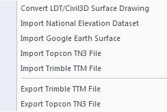
In addition to LandXML, Carlson gives you a bunch of different ways to import, export and convert data to and from other desktop, field and machine control software. For instance, here’s the menu for Import/Export Surface Data that’s in Construction, Civil & Survey:
Civil 3d data is, by far, the most difficult data to share… In some cases it’s literally impossible to save data such as points and surfaces and be able to use it in any previous version of Civil 3d!
However, you can use the EXPORTTOAUTOCAD commands in Civil 3d to basically explode all the custom entities so they can be opened and used in other programs or in earlier versions of Civil 3d. Of course, by exploding everything, you essentially lose any perceived benefit of working on the drawing in Civil 3d.
Some content on this website was prepared with AI assistance. Please verify important information with the manufacturer or original source before making purchasing or financial decisions.
If you find the material on this website helpful, please consider supporting That CAD Girl by purchasing our products or services.
If you are interested in purchasing products or services we do not offer, we would love to refer you to one of our Trusted Partners. Please click here to send us a message with your request.
How can I install Land Desktop on a Windows 7 computer?
+
I had actually forgotten about this but recently had to re-install Land Desktop myself and I figured it was worth sharing. This method is not guaranteed but it just might work.
Instead of trying to install Land Desktop from the original DVD, try copying the contents of the DVD to a new folder on the hard drive of the Windows 7 machine. Then, run the installation from there by clicking on the Setup.exe file.
I haven’t tried this with anything newer than Windows 7 but it worked flawlessly on my Windows 7 64 bit computer.
Some content on this website was prepared with AI assistance. Please verify important information with the manufacturer or original source before making purchasing or financial decisions.
If you find the material on this website helpful, please consider supporting That CAD Girl by purchasing our products or services.
If you are interested in purchasing products or services we do not offer, we would love to refer you to one of our Trusted Partners. Please click here to send us a message with your request.
I’m just learning CAD. What’s the one piece of advice you’d give to make me a power user?
+I lost one of my first CAD jobs because I’d been away from CAD work for about 6 months and I was given a CAD test during an interview. While my interviewer watched, I tried to draw a roadway intersection on a computer that had a 2-button mouse and a newly installed copy of AutoCAD R10. I quickly realized that in all my prior work and training I’d become too dependent on macros, LISP routines and the dreaded digitizer tablet (remember those?!). In those days we only had a Command: line and a right sidebar menu – not a toolbar to be found!
Commands like ERASE, COPY and MOVE were easy to remember but FILLET? Forget about it. I tanked.
I found a computer with CAD to practice and refresh a bit and made it through my next interview and test but I never forgot the experience. Although they were available if I wanted them, I swore off the digitizer tablet and even stopped using command aliases for a long time and typed in the whole long command in most cases. As new versions came out and new menus and toolbars came and went, I realized that the commands entered at the Command: line changed very little from version to version. Unlike co-workers, I didn’t panic with each new version install and had no problems working on someone else’s computer if necessary because it didn’t matter if I couldn’t find my magic toolbar.
Some content on this website was prepared with AI assistance. Please verify important information with the manufacturer or original source before making purchasing or financial decisions.
If you find the material on this website helpful, please consider supporting That CAD Girl by purchasing our products or services.
If you are interested in purchasing products or services we do not offer, we would love to refer you to one of our Trusted Partners. Please click here to send us a message with your request.
Are Express Tools available in Carlson?
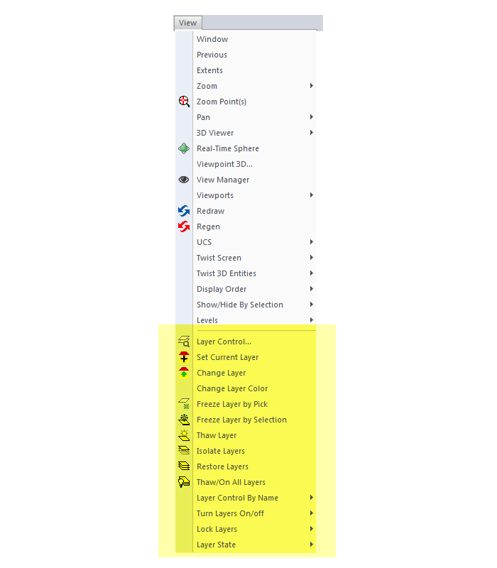
+Carlson Layer Tools are highlighted in the View menu below:

Some content on this website was prepared with AI assistance. Please verify important information with the manufacturer or original source before making purchasing or financial decisions.
If you find the material on this website helpful, please consider supporting That CAD Girl by purchasing our products or services.
If you are interested in purchasing products or services we do not offer, we would love to refer you to one of our Trusted Partners. Please click here to send us a message with your request.
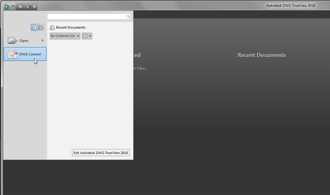
Use DWG Convert to save DWG files to an earlier version
+DWG TrueView is FREE utility available from Autodesk. They release a new version of this program every year, just like their other products.
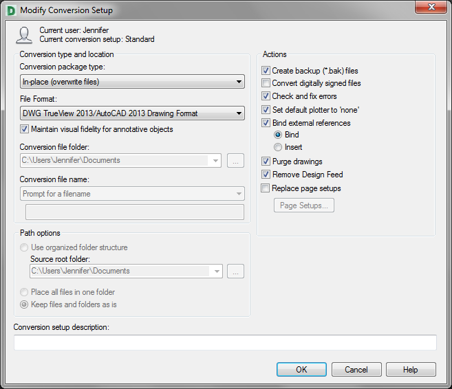
With the True Convert utility you can convert any newer version DWG or DXF to any earlier version. I’d recommend you enable the option that creates a .bak file with the original just in case you need it later.
Inside the True Convert utility you can also enable several other options that will run routines such as Audit, Purge, XREF Binding, etc. during the convert process.
You can download DWG True View 2018 here.
Some content on this website was prepared with AI assistance. Please verify important information with the manufacturer or original source before making purchasing or financial decisions.
If you find the material on this website helpful, please consider supporting That CAD Girl by purchasing our products or services.
If you are interested in purchasing products or services we do not offer, we would love to refer you to one of our Trusted Partners. Please click here to send us a message with your request.
Find Answers on your new That CAD Girl Portal
+Find Answers on your new That CAD Girl Portal
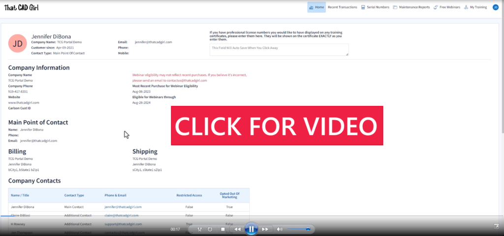
If you (or your company) have ever requested a proposal or invoice from That CAD Girl – Congrats! You have a portal!
Every portal is specific for the email address we have on file for you, so – Click here to access That CAD Girl’s Customer Portal then enter your email address.
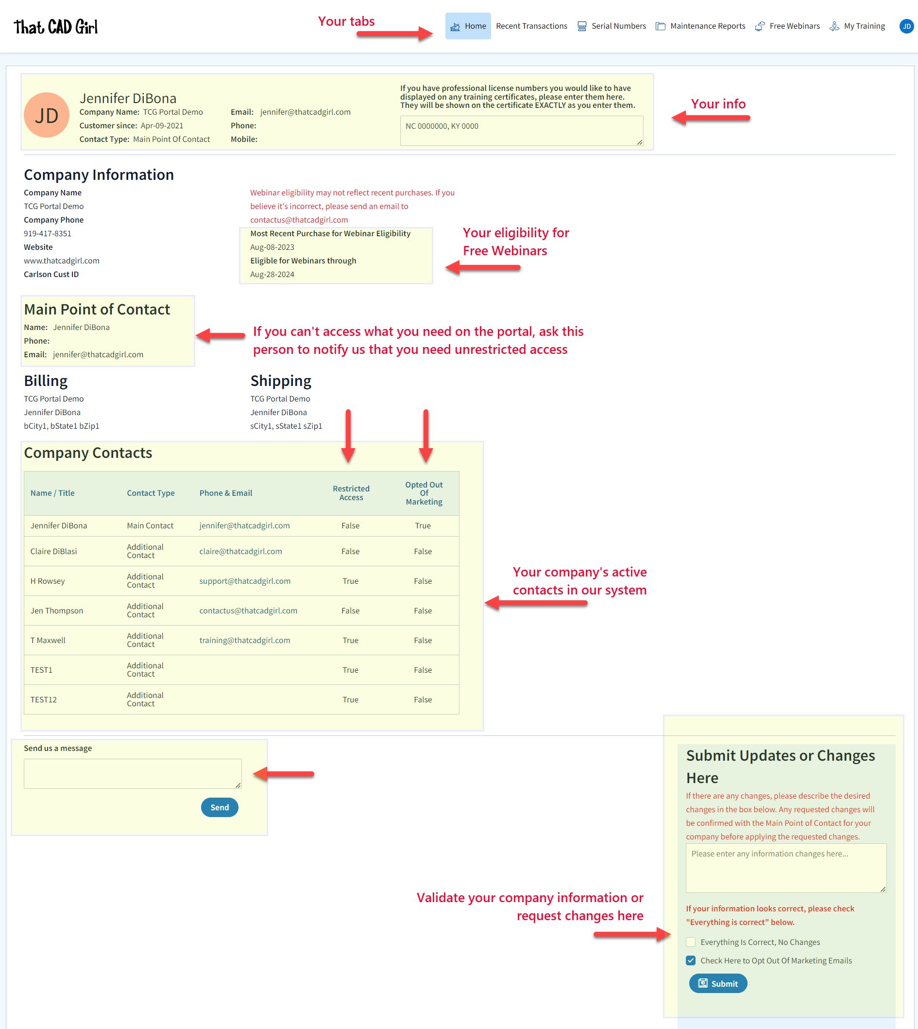
The availability of tabs on your portal will depend on whether you have been granted Full Access by the primary contact in your company or if you have Restricted Access. Everyone will have Home, Free Webinars and My Training tabs while those with Full Access will have access to Recent Transactions, Serial Numbers and Maintenance Reports.
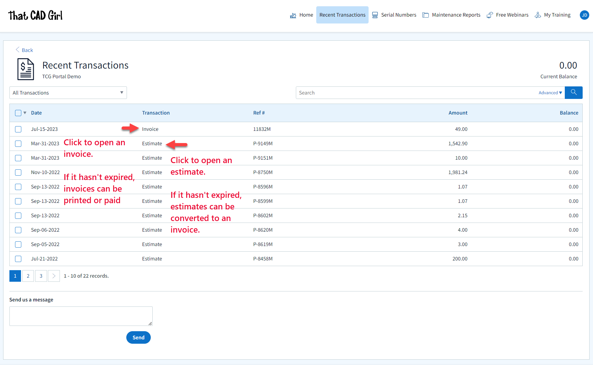
Clicking on an Estimate – When viewing an Estimate (Proposal) in Recent Transactions, you have different options depending on whether the Estimate has been previously converted to an invoice, is active (unexpired) or is past due (expired).
For active (unexpired) and unconverted Estimates, you can click “Accept & Pay” to convert the Estimate to an Invoice and proceed directly to our payments screen or click “Create Invoice” to convert the Estimate to an invoice and proceed to the Invoice screen.
For past due (expired) or previously converted Estimates, you only have the “Print” button that allows you to export to a PDF.
NOTE: Once an Estimate has been converted to an Invoice using either option, you must return to the Recent Transactions table and open the Invoice to pay.
Clicking on an Invoice – When viewing an Invoice in Recent Transactions, you have different options depending on whether the Invoice is active or past due.
For active (unexpired) Invoices, you can click “Pay Now” to proceed to our payment screen.
For past due (expired) Invoices, you only have the “Print” button that allows you to export to a PDF.
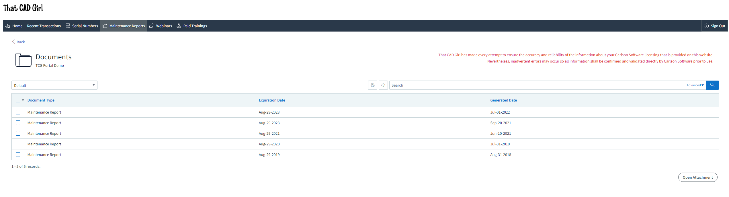
DISCLAIMER: That CAD Girl has made every attempt to ensure the accuracy and reliability of the information about your Carlson Software licensing that is provided on this website. Nevertheless, inadvertent errors may occur so all information shall be confirmed and validated directly by Carlson Software prior to use.
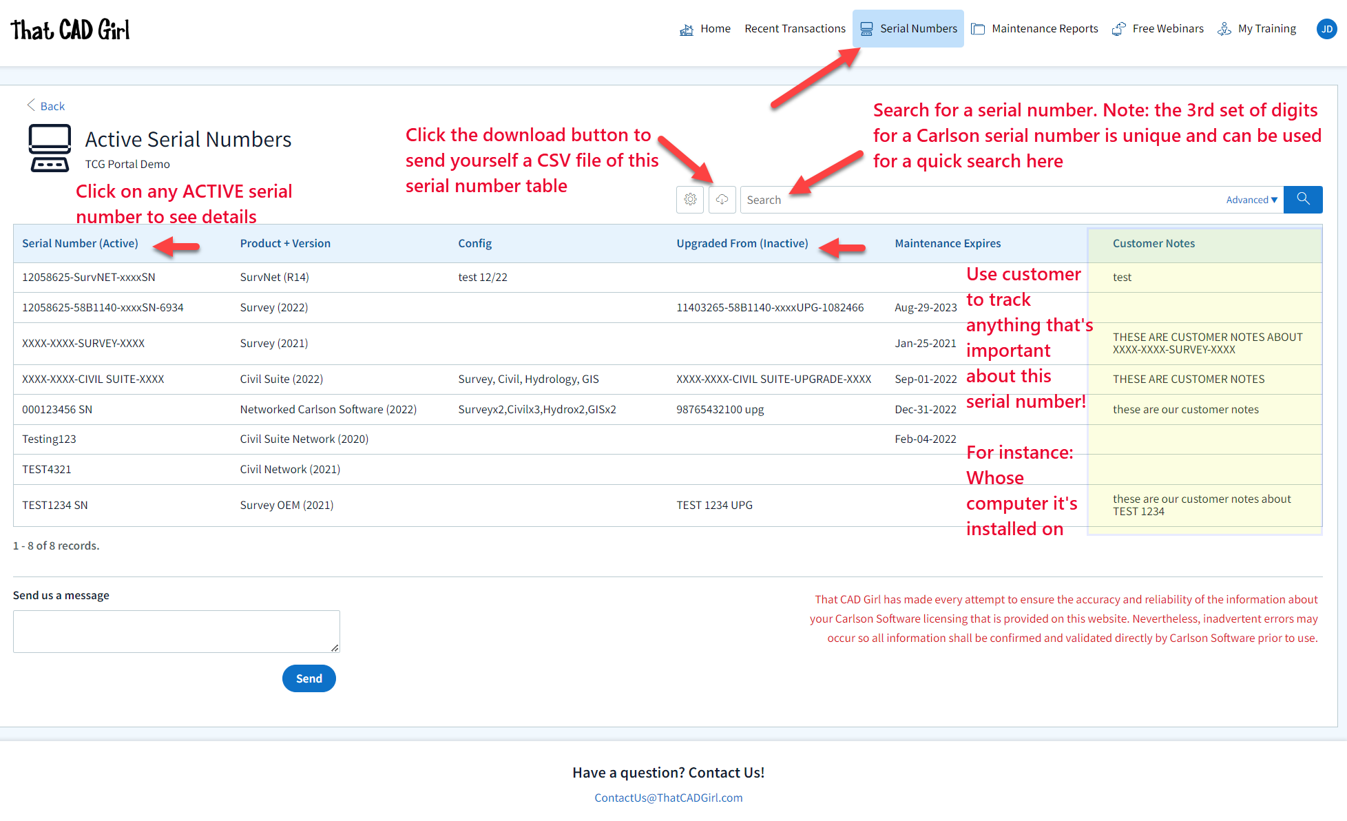
Also, clicking on any serial number in the list brings you to a details page where you can add any “Customer Notes” that are helpful to you such as the user name, location or even the Change Key associated to that installation. You can also find the link to download and link to installation instructions.
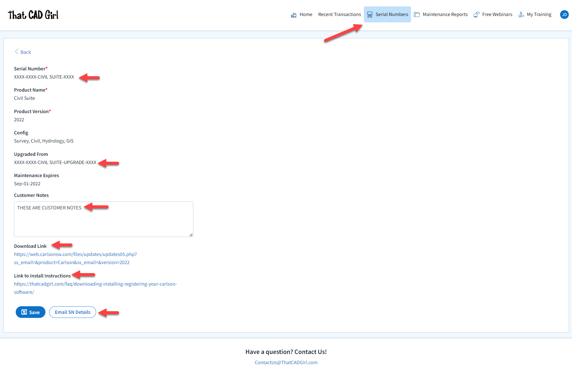
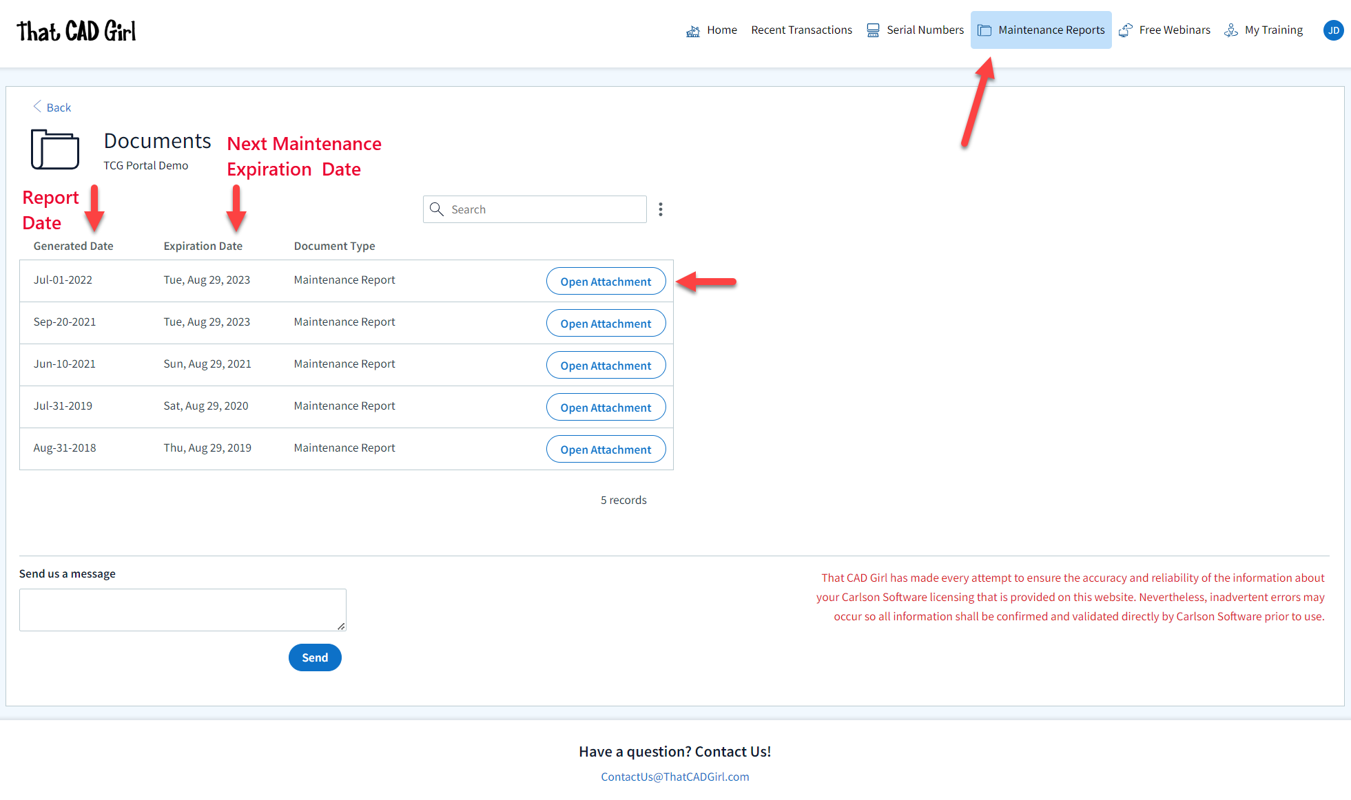
DISCLAIMER: That CAD Girl has made every attempt to ensure the accuracy and reliability of the information about your Carlson Software licensing that is provided on this website. Nevertheless, inadvertent errors may occur so all information shall be confirmed and validated directly by Carlson Software prior to use.
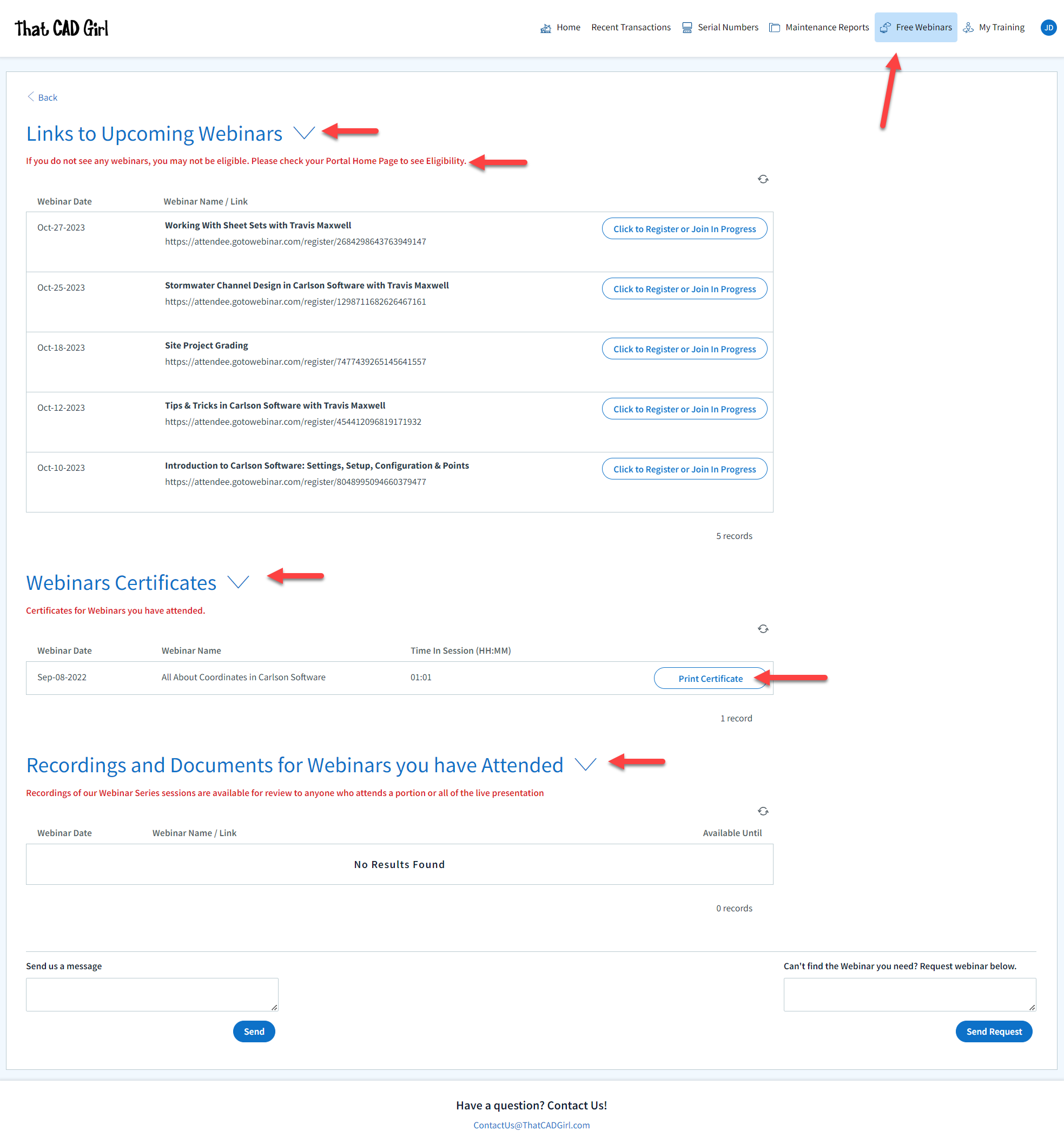
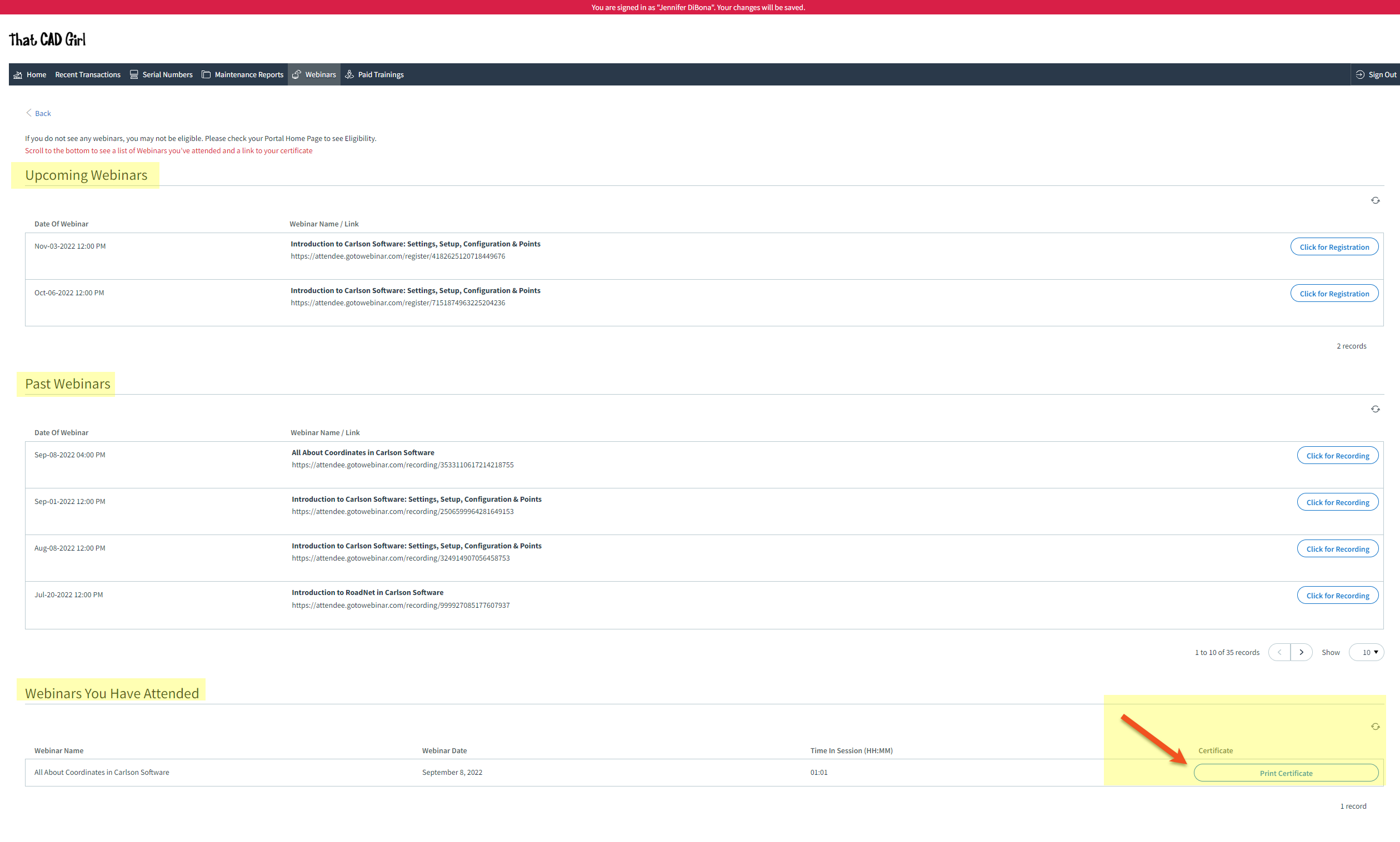
- A list of Upcoming sessions in our Webinar Series with links to pre-register
- A list of webinars that you attended and a button to download a Certificate of Attendance. Note: You can add your professional license numbers on your Home tab and they will appear on your certificates.
- A list of recordings of webinars that you attended
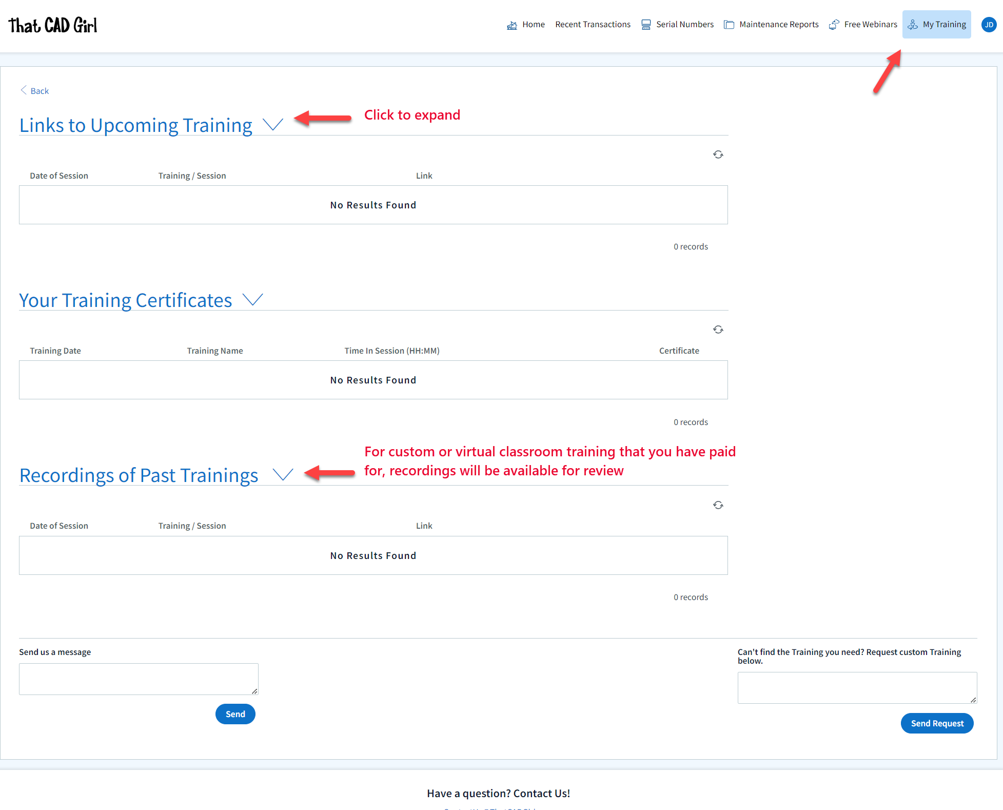
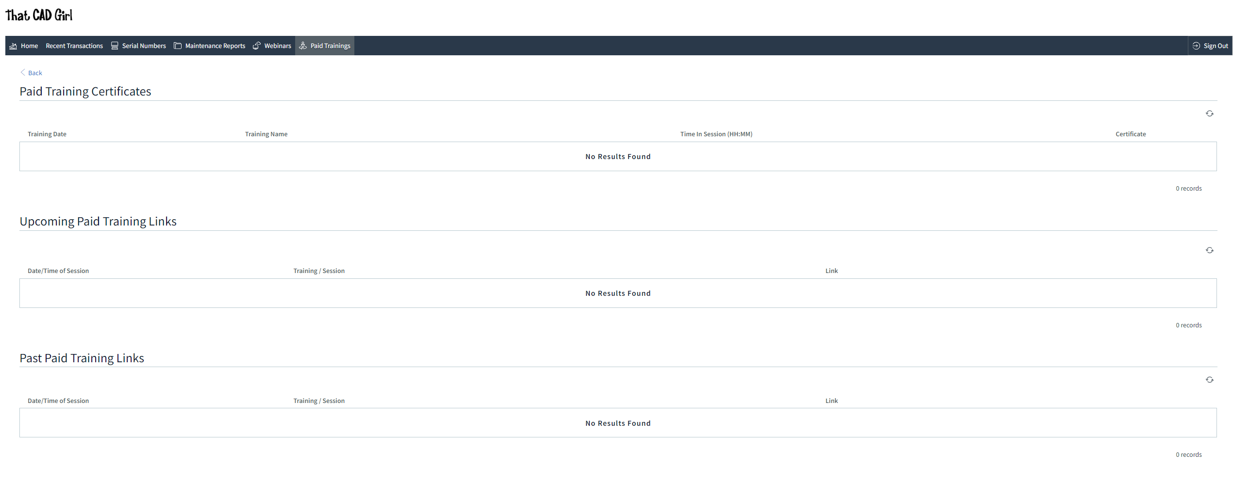
- A list of Upcoming Training sessions that have already been paid for with links to pre-register
- A list of Past Training sessions the user has paid for and attended with a link to download a Certificate of Attendance
- A list of Past Training sessions with links to the recording
Find Answers on your new That CAD Girl Portal
If you have ever requested a proposal or invoice from That CAD Girl – Congrats! You have a portal!
Every portal is specific for the email address we have on file for you and you can access yours by following this link and entering your email address.
The availability of tabs on your portal will depend on whether you have been granted Full Access by the primary contact in your company or if you have Restricted Access. Everyone will have Home, Webinars and Paid Training tabs while those with Full Access will have access to Transactions, Serial Numbers and License Reports.
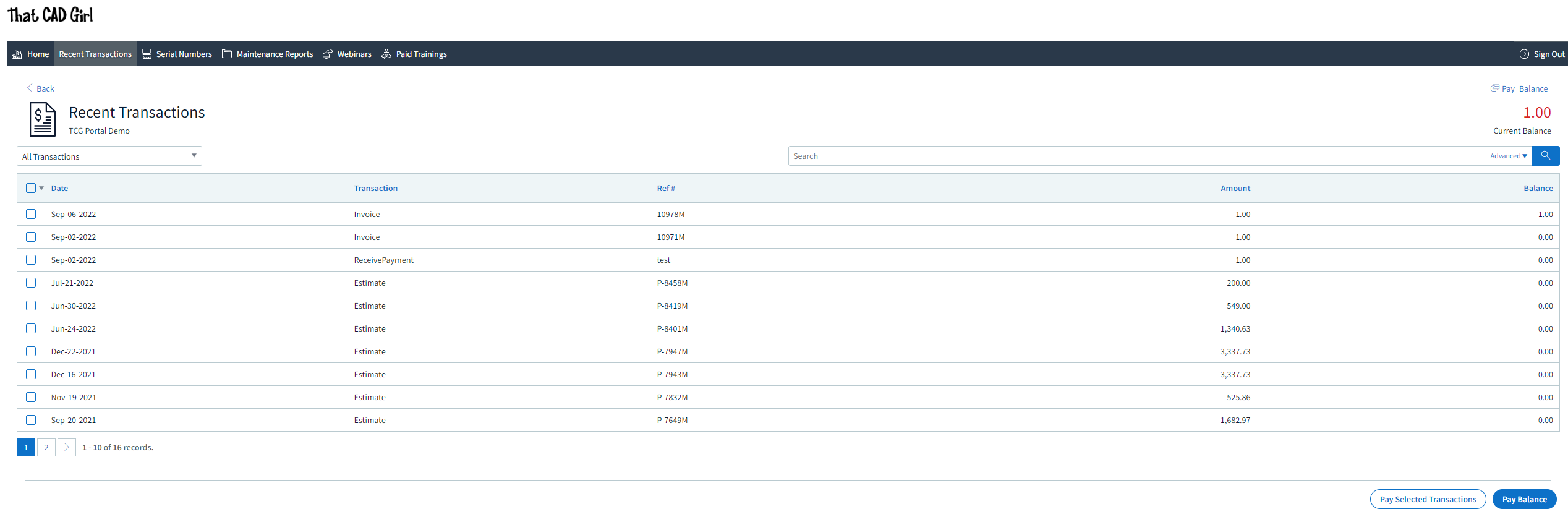
DISCLAIMER: That CAD Girl has made every attempt to ensure the accuracy and reliability of the information about your Carlson Software licensing that is provided on this website. Nevertheless, inadvertent errors may occur so all information shall be confirmed and validated directly by Carlson Software prior to use.

Also, clicking on any serial number in the list brings you to a details page where you can add any “User Notes” that are helpful to you such as the user name, location or even the Change Key associated to that installation. You can also find the link to download and link to installation instructions.
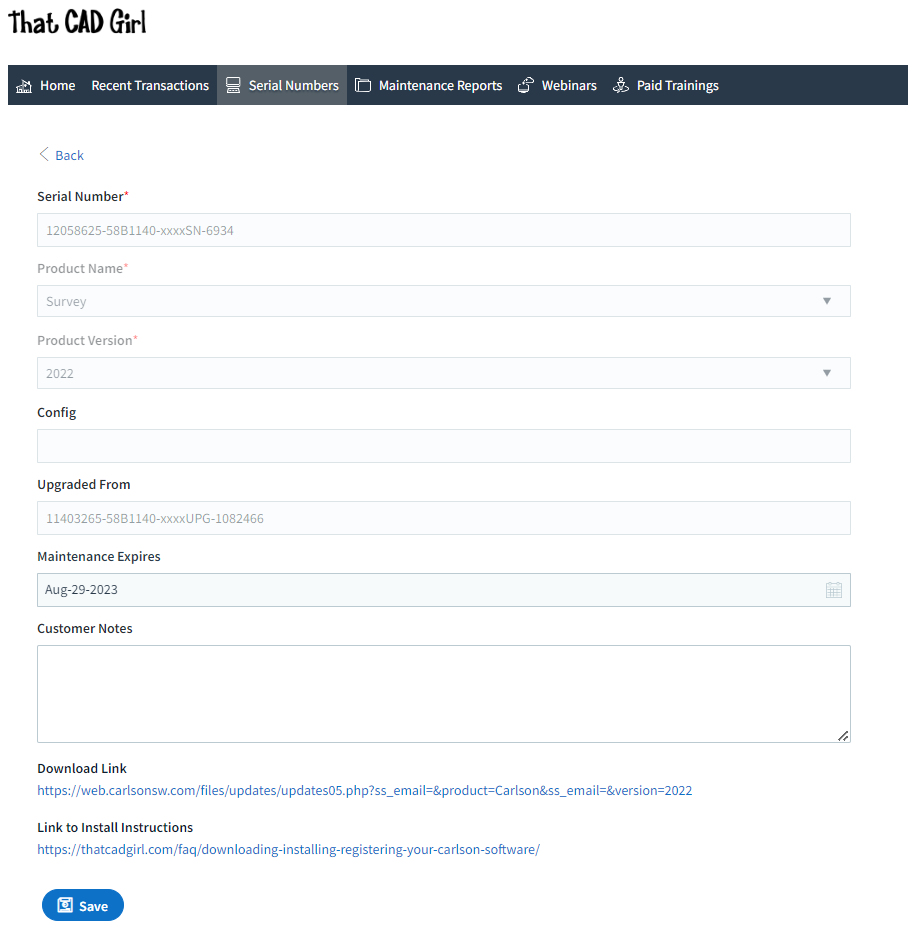
DISCLAIMER: That CAD Girl has made every attempt to ensure the accuracy and reliability of the information about your Carlson Software licensing that is provided on this website. Nevertheless, inadvertent errors may occur so all information shall be confirmed and validated directly by Carlson Software prior to use.
- A list of Upcoming sessions in our Webinar Series with links to pre-register
- A list of Past sessions in our Webinar Series with links to the recording
- A list of sessions the user has attended with a link to download a Certificate of Attendance
- A list of Paid Training sessions the user has attended with a link to download a Certificate of Attendance
- A list of Upcoming Paid Training sessions that have already been paid for with links to pre-register
- A list of Past Paid Training sessions with links to the recording
Some content on this website was prepared with AI assistance. Please verify important information with the manufacturer or original source before making purchasing or financial decisions.
If you find the material on this website helpful, please consider supporting That CAD Girl by purchasing our products or services.
If you are interested in purchasing products or services we do not offer, we would love to refer you to one of our Trusted Partners. Please click here to send us a message with your request.