Picks and Clicks: Dynamic Blocks
This article originally appeared in the December 2010 issue of Professional Surveyor magazine.
Welcome to the first installment of this new column highlighting favorite AutoDesk, IntelliCAD, and Carlson Software features. My goal is to help you reduce your number of “picks and clicks” while using these pieces of software so you can be more efficient, saving time and money.
Because many of us are hanging onto our current software versions for as long as possible these days, I will try to avoid reviewing features that were released in “last week’s” version and will instead write about commands and features that have been around for at least a few years.
First: A little about my background and experience. My first CAD class was with AutoCAD 9 and DCA software as part of my Surveying Technology coursework in college. After graduating, I worked for various consulting, engineering, and surveying companies where I used mostly the Autodesk family of products: AutoCAD, AutoCAD Map, Land Desktop, and Civil Design with brief detours into the MicroStation, GeoPak and Eagle Point worlds.
It was during this time that I started teaching basic CAD and civil/survey CAD classes at local community colleges. I then joined a local Autodesk and Carlson Software reseller to help start and build their training division. In 2004 I stepped out to begin working for myself as That CAD Girl. I offer Carlson Software sales; training and support for Autodesk, Carlson and IntelliCAD; and associated consulting services while specializing in CAD standards development and surface modeling training. My website is at www.thatcadgirl.com. And my surveying column is now here!
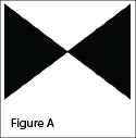
Water Valve
(Figure A)
One of my favorite, fairly new AutoCAD features is Dynamic Blocks, which was first introduced in AutoCAD 2006. A Dynamic Block is simply a standard block that has been enhanced with additional functionality. You may have seen examples of complex Dynamic Blocks that allow you to change the size (by stretching) or the orientation (by mirroring) only pieces of a block without having to EXPLODE it. But, you can also save many picks and clicks by giving your existing blocks a facelift with some simple Dynamic functionality. Let’s start with a standard symbol or block that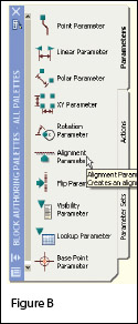 most everyone will already have saved in a block library somewhere: a Water Valve.
To use the standard version of this block in a drawing, we usually have to:
- Use the INSERT command to bring the block into the drawing.
- Use a NEArest OSNAP to position the block on a line representing a waterline.
- Use the ROTATE command with the Reference option to align the block with the line.
- Whew!
Two minutes (or less) in the Block Editor will eliminate steps 2-4 (at right.)
- Insert the standard Water Valve block into your current drawing.
- Left-click to select the block.
- Right-click and open the Block Editor from the shortcut menu.
- On the “Parameters” tab of the Block Authoring Palette, select the tool to create an Alignment Parameter. [Figure B]
- The Command: line prompts you to, “Specify base point of alignment or [Name]:”. Use your
 INTersection OSNAP to specify the insertion point for the block.
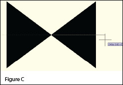
 - Next, you are prompted to “Specify alignment direction or alignment type [Type] <Type>:”. [Figure C] Turn Ortho On and pick a point directly to the right of the insertion point.
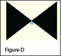
- When finished, the block with its new Alignment icon will look like this in the Block Editor: [Figure D]
- Pick the Close Block Editor button at the top of the screen and then pick “Yes” when prompted to save the block definition.
Using the Dynamic Block
Once you are back in the main drawing screen, the original instance of the block will have been updated.
- Left-click the block to see the new Alignment icon.
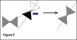
- Left-click on the blue Alignment icon. This allows you to “pick up” the block and move it. [Figure E]
 Drag the block on top of a line in your drawing that represents a waterline. You will notice that, once your crosshairs are positioned over the line, the block automatically aligns itself to the line, and, in addition, the NEArest OSNAP is enabled allowing you to position and snap the block directly onto the line.
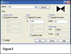
- Use the Insert command to draw additional copies of the block into the drawing. Notice that the thumbnail image of blocks with Dynamic parameters displays a lightning bolt icon so as to differentiate Dynamic Blocks from standard blocks. [Figure F]
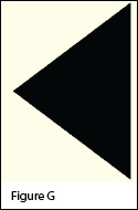 Waterline Reducer
[Figure G]
Another often-used water-utility symbol that can benefit from the addition of Dynamic properties is the waterline Reducer. This symbol is used to indicate a change in the size of a waterline. In addition to an Alignment Parameter, this symbol needs a Flip Parameter that allows us to easily mirror it to change its direction. Unlike an Alignment Parameter, adding a Flip Parameter to a block also requires that you add a second Dynamic Block component called an Action. Giving a block “flip-ability” requires a few more steps, but is still rather easy.
- Repeat steps 1-7 as described for the Water Valve to insert the “Reducer” block into the drawing and add an Alignment Parameter to it.
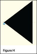 The Reducer with its Alignment icon is shown at left: [Figure H]
 - Turn Ortho On.
- Pick the Flip Parameter icon on the Block Authoring Palette. [Figure I]
- The Command: line prompts you to “Specify base point of reflection line or [Name/Label/Description/Palette]:”. Use your ENDPoint OSNAP to specify the insertion point for the block (use the same point as for the Alignment Parameter).
- The Command: line next prompts you to “Specify endpoint of reflection line:”. With Ortho On, pick a point directly above the “Base Point” specified in the previous step. These two points define the “reflection line” for mirroring.
- You are then prompted to “Specify label location:”. Pick a point somewhere just above the
 Reducer symbol. The label reads, “Flip state”.
 - Use the MOVE command, with Ortho On, to slide the Flip icon above the block.
- The Reducer [Figure J] with its Alignment [Figure K] and Flip icons [Figure L] are shown at right. A Warning icon [Figure M] is also displayed indicating a missing
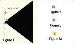 Action component.
 - On the “Actions” tab of the Block Authoring Palette, select the tool to create a Flip Action. [Figure N]
- The Command: line prompts you to “Select Parameter:”. Select any part of the Flip Parameter including the label, the Flip icon, or the Warning icon.
- Next, you are prompted to “Specify selection set for action. Select Objects:”. Select the Flip icon and all entities that make up the block/symbol.
- You are then prompted to “Specify action location:”. Pick a point somewhere near the “Flip state” label. The label has a lightning bolt icon and reads, “Flip”.
- Pick the Close Block Editor button at the top of the screen and then pick “Yes” when prompted to save the block definition.
Using the Dynamic Block
 As before, once you are back in the main drawing screen, the original instance of the block will have been updated.
- Left-click the block to seea the new Alignment and Flip icons.
- Left-click on the blue Alignment icon to move it onto a line representing a waterline.
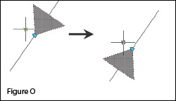
- Left-click on the blue Flip icon to mirror the block along the line.
- Use the Insert command to draw additional copies of the block into the drawing. [Figure O]
Note that the steps change the block definition in the current drawing only. The WBLOCK command must be used to save the block out as an external Drawing (.dwg) file.
This article originally appeared in the December 2010 issue of Professional Surveyor magazine.